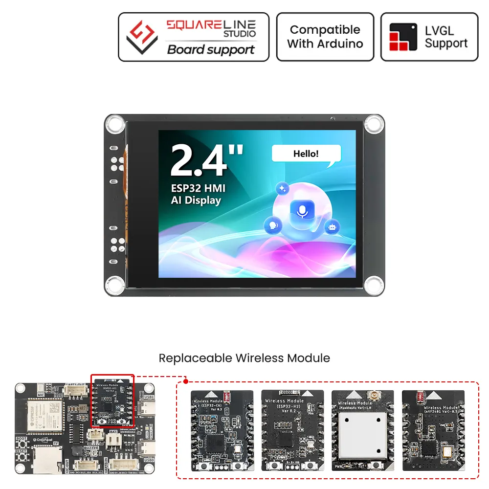
CrowPanel Advance 2.4-HMI ESP32 AI Display
Model DIS01624A
Pin Output:
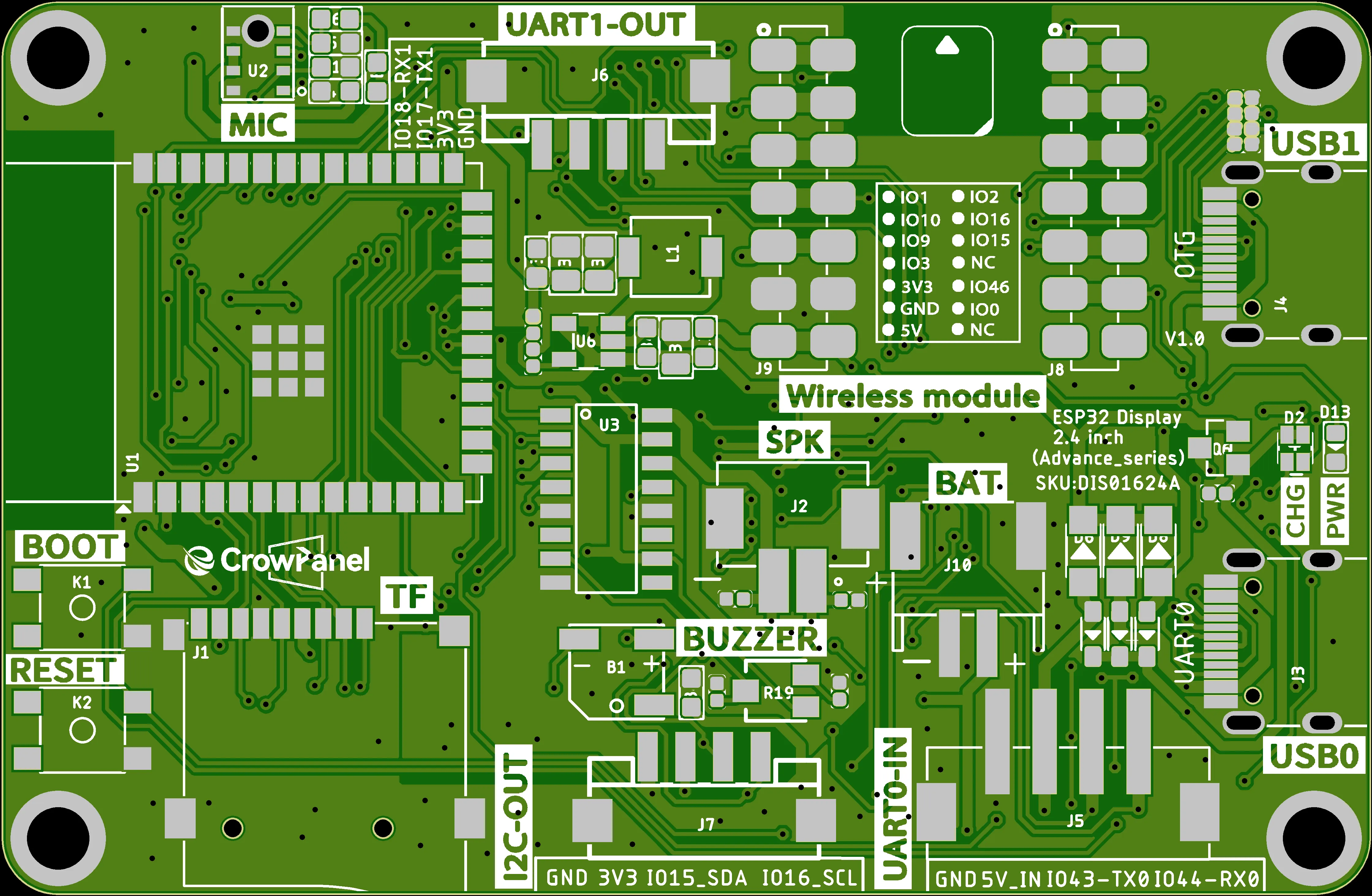
Functional description of the product's internal interfaces:
| Pin Name | Description | Connector Type |
|---|---|---|
| SPK | Output audio signals to connect to speakers. The main board comes with a power amplifier chip circuit. | PH2.0-2P |
| PWR | Power LED. | |
| RST | Reset button. Press it to reset the system. | |
| boot | ||
| UART1-OUT | Builds communication between Logic modules, including the serial communication module and the print module. | HY2.0-4P |
| UART0-IN | Input power supply and serial communication functionality | XH2.54-4P |
| I2C-OUT | Establish communication between the microcontroller and peripheral devices. | HY2.0-4P |
| BAT | Connect the lithium battery. (with battery charging circuit)(Input voltage: 3.7–4.2 V) | PH2.0-2P |
Product External Interface Functions:
| 2.8-inch HMI port | pin number | Electrical Characteristics |
|---|---|---|
| UART1-OUT | RX(IO18); TX(IO17) RX; | Output voltage: 3.3V Output current: 1A max. Use: Power supply output and communication. |
| UART0-IN | RX(IO44); TX(IO43) RX; | Input voltage: 5V ± 5%. 5.5V max. Input current: 2A max. Purpose: Power supply input and communication. |
| I2C | SDA(IO15); SCL(IO16) ; | Output voltage: 3.3V Output current: 1A max. Use: Power supply output and communication. |
| SPK | I2S_LRCLK(IO11);I2S_BCLK(IO13);I2S_SDIN(IO12); | Maximum output current: 20mA Signal type: 3.3V logic level, digital control signal |
| SD Card Slot | MOSI(IO6); MISO(IO4); CLK(IO5); CS(3.3V) | Maximum output current: 20mA Signal type: 3.3V logic level, digital control signal |
| LCD Backlight | IO38 | Maximum output current: 20mA Signal type: 3.3V logic level, digital control signal |
| I2S MIC | MIC_SD(IO10);MIC_WS(IO3);MIC_CLK(IO9) | Maximum output current: 20mA Signal type: 3.3V logic level, digital control signal |
| BUZZER | IO8 | Maximum output current: 20mA Signal type: 3.3V logic level, digital control signal |
Switching Function Keys:
| IO45 level | effective function |
|---|---|
| 1 | MIC |
| 0 | WM(wireless module) |
Schematic:
ESP32-S3 and ISP Display Wiring Pins:
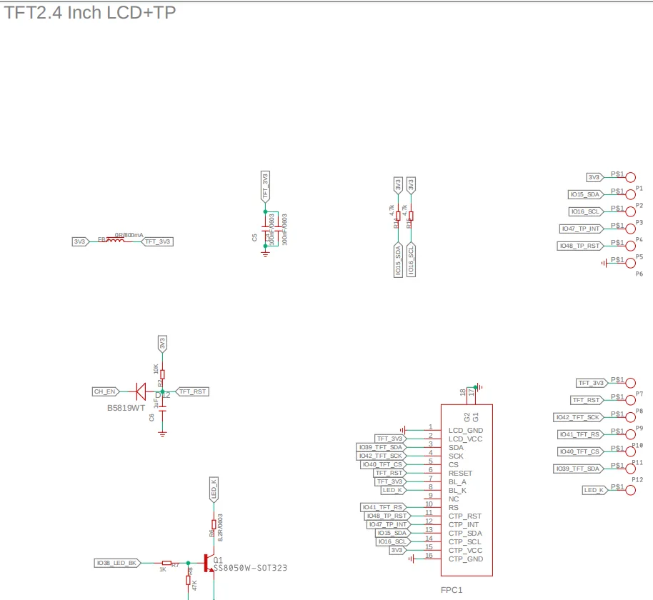
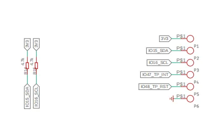
ESP32-S3 and Touch Driver Wiring:
i2c address: 0x38.
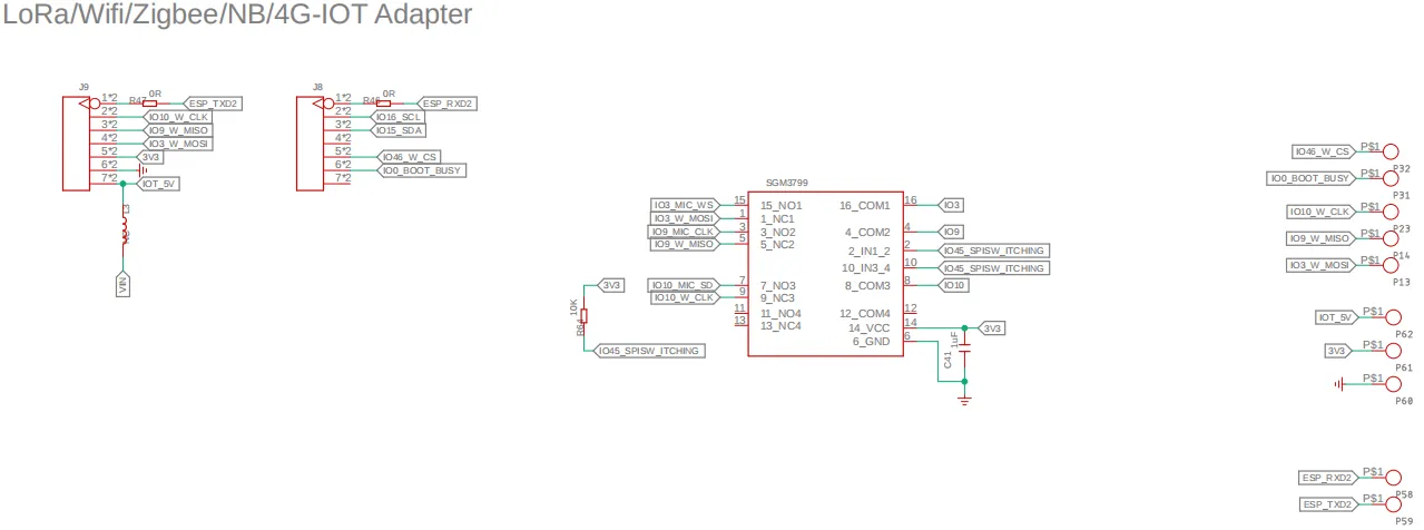
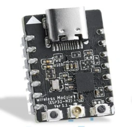
ESP32-S3 and wireless module wiring pins:
Switching Function Keys:
| IO45 level | effective function |
|---|---|
| 1 | MIC |
| 0 | WM(wireless module) |
Wireless module pins:
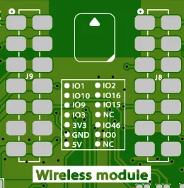
| IO1 | IO2 |
|---|---|
| IO10 | IO16 |
| IO9 | IO15 |
| IO3 | NC |
| 3V3 | IO46 |
| GND | IO0 |
| 5V | NC |
V1.1 upgraded, optimized the amplifier circuit, better sound quality, and use IO21 to control mute. i2s_mic changed to two pins IO9 and IO10 control.

Version 1.2
Only the button component has been updated. All other hardware and I/O pins remain the same as in the previous version.
Platforms Supported
| Arduino IDE | ESP-IDF | PlatformIO |
|---|---|---|
 | ||
| Arduino IDE View Tutorials -- V1.0/V1.1/V1.2 | ESP-IDF View Tutorials -- V1.0/V1.1/V1.2 | platfoemIO View Tutorials -- V1.0/V1.1/V1.2 |
| ESPHome | SquareLine Studio | Meshtastic |
|---|---|---|
 | ||
| ESPHome View Tutorials -- V1.0/V1.1/V1.2 | SquareLine Studio View Tutorials -- V1.0/V1.1/V1.2 |  |
| Thread Wireless | ESP-matter |
|---|---|
 | |
 | |
Resources
Github link:
(This GitHub link usually may contain 3D files, schematics, program code, factory firmware, factory sourcecode and other materials. Please click to view.)
Wireless link:
How to buy
Please visit this page to purchase ESP32 Display-2.4 inch(Advance_Series).
Support
If you encounter any issues while using the service, you can contact us via the social media links in the bottom-right corner of elecrow or send an email to techsupport@elecrow.com for technical support.