NRF24L01+PA+LNA Wireless Module
Description
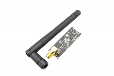
NRF24L01P + PA + LNA wireless module operates in Free license 2.4G ISM band, you can do point to point application and can also be composed of star network. The Data transmission chip NRF24L01+, and match with the department's professional design, Add the the chip of power PA and LNA, RF switch, band pass filter composed of a professional full two-way RF power amplifier, making the effective communication distance has been greatly expanded. Small size: 45.54mm x 16.46mm, easy to embed in any space-constrained products, customers can use the SPI port of Arduino or any other MCU to control NRF24L01P + PA + LNA, Wireless module to complete long distance wireless data transmission system desige.
Model:WRW24015R
Features
- It uses 2.4G global open ISM band, with license free.
- Transmit power is greater than +20 dbm.Support six-channel data reception. 2Mbit/s speed makes high-quality VoIP possible Low
- operating voltage: 2.7 to 3.6V
- Multi-frequency points: 125 frequency points meet the needs of multi-point communications and frequency hopping.
- Low cost: integrated with high-speed signal processing parts associated with RF protocol, such as: automatically re-send lost packets and generate acknowledge signal; SPI interface facilitates the communication with MCU I/O port.
- Facilitate the development for customers, without development RF part.
- Software programming is fully compatible with NRF24L01 modules.Size: 37.4mm * 16.6mm
- Applications: remote control, telemetry, wireless meter reading, access control systems, residential paging, industrial data acquisition systems, wireless tags, identification, contactless RF smart card, small wireless data terminal, fire
- safety systems, wireless remote control systems, bio-signal acquisition, wireless 232, wireless 422/485 data communications.
Specification
- Operating Frequency: 2400MHz ~ 2524MHz
- Modulation: GMSK
- Transmit power: more than +20 dbm, 50Ω
- Receiver sensitivity:-95dbm
- Operating voltage: 2.7V ~ 3.6V
- Max Emission current: 115mA
- Max Receive current: 45mA
- Operating temperature: -45 degrees to +85 degrees
- Storage temperature: -45 degrees to +125 degrees
- Gain Of PA: 20 dB
- Gain Of LNA: 10 dB
Interface Function
| PIN | Function | Direction | |
|---|---|---|---|
| Pin1 | GND | Ground | |
| Pin2 | VCC | VCC, 1.9~3.6V | |
| Pin3 | CE | Operating Mode,RX/TX | In |
| Pin4 | CSN | SPI chip select | In |
| Pin5 | SCK | SPI clock | In |
| Pin6 | MOSI | SPI Input | In |
| Pin7 | MISO | SPI Output | Out |
| Pin8 | IRQ | Interrupt Output | Out |
Usage
With Arduino
The nRF24L01 module can be controlled in many ways, one of which is Arduino or Crowduino. We tried and tested it, then made a demo. Let’s see how it works with Arduino.
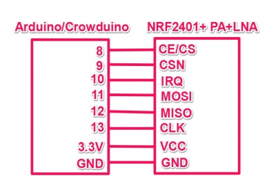
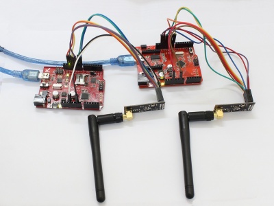
1.Hardware Connection.
First of all, of course, you need two Arduino boards and at least two RF modules, one to transmit and the other to receive.
2.Download the code below into the TX Arduino (transmit) — This code will drive the nRF24L01 module to send out data form 0×00 to 0xFF .
/** ******************************************************************
**   SPI-compatible                                                 **
**   CS -  to digital pin 8                                         **
**   CSN - to digital pin 9   (SS pin)                              **
**   IRQ - to digital pin 10  (IRQ pin)                             **
**   MOSI - to digital pin 11 (MOSI pin)                            **
**   MISO - to digital pin 12 (MISO pin)                            **
**   CLK - to digital pin 13  (SCK pin)                             **
*********************************************************************/

#include <SPI.h>
#include "API.h"
#include "nRF24L01.h"

//***************************************************
#define TX_ADR_WIDTH    5   // 5 unsigned chars TX(RX) address width
#define TX_PLOAD_WIDTH  32  // 32 unsigned chars TX payload

unsigned char TX_ADDRESS[TX_ADR_WIDTH]  =
{
  0x34,0x43,0x10,0x10,0x01
}; // Define a static TX address

unsigned char rx_buf[TX_PLOAD_WIDTH] = {0}; // initialize value
unsigned char tx_buf[TX_PLOAD_WIDTH] = {0};
//***************************************************
void setup()
{
  Serial.begin(9600);
  pinMode(CE,  OUTPUT);
  pinMode(CSN, OUTPUT);
  pinMode(IRQ, INPUT);
  SPI.begin();
  delay(50);
  init_io();                        // Initialize IO port
  unsigned char sstatus=SPI_Read(STATUS);
  Serial.println("*******************TX_Mode Start****************************");
  Serial.print("status = ");
  Serial.println(sstatus,HEX);     // There is read the mode’s status register, the default value should be ‘E’
  TX_Mode();                       // set TX mode
}

void loop()
{
  int k = 0;
  for(;;)
  {
    for(int i=0; i<32; i++)
        tx_buf[i] = k++;
    unsigned char sstatus = SPI_Read(STATUS);                   // read register STATUS's value
    if(sstatus&TX_DS)                                           // if receive data ready (TX_DS) interrupt
    {
      SPI_RW_Reg(FLUSH_TX,0);
      SPI_Write_Buf(WR_TX_PLOAD,tx_buf,TX_PLOAD_WIDTH);       // write playload to TX_FIFO
    }
    if(sstatus&MAX_RT)                                         // if receive data ready (MAX_RT) interrupt, this is retransmit than  SETUP_RETR
    {
      SPI_RW_Reg(FLUSH_TX,0);
      SPI_Write_Buf(WR_TX_PLOAD,tx_buf,TX_PLOAD_WIDTH);      // disable standy-mode
    }
    SPI_RW_Reg(WRITE_REG+STATUS,sstatus);                     // clear RX_DR or TX_DS or MAX_RT interrupt flag
    delay(1000);
  }
}

//**************************************************
// Function: init_io();
// Description:
// flash led one time,chip enable(ready to TX or RX Mode),
// Spi disable,Spi clock line init high
//**************************************************
void init_io(void)
{
  digitalWrite(IRQ, 0);
  digitalWrite(CE, 0);          // chip enable
  digitalWrite(CSN, 1);                 // Spi disable
}

/************************************************************************
**   * Function: SPI_RW();
 *
 * Description:
 * Writes one unsigned char to nRF24L01, and return the unsigned char read
 * from nRF24L01 during write, according to SPI protocol
************************************************************************/
unsigned char SPI_RW(unsigned char Byte)
{
  return SPI.transfer(Byte);
}

/**************************************************/

/**************************************************
 * Function: SPI_RW_Reg();
 *
 * Description:
 * Writes value 'value' to register 'reg'
/**************************************************/
unsigned char SPI_RW_Reg(unsigned char reg, unsigned char value)
{
  unsigned char status;

  digitalWrite(CSN, 0);                   // CSN low, init SPI transaction
  SPI_RW(reg);                            // select register
  SPI_RW(value);                          // ..and write value to it..
  digitalWrite(CSN, 1);                   // CSN high again

  return(status);                   // return nRF24L01 status unsigned char
}
/**************************************************/

/**************************************************
 * Function: SPI_Read();
 *
 * Description:
 * Read one unsigned char from nRF24L01 register, 'reg'
/**************************************************/
unsigned char SPI_Read(unsigned char reg)
{
  unsigned char reg_val;

  digitalWrite(CSN, 0);                // CSN low, initialize SPI communication...
  SPI_RW(reg);                         // Select register to read from..
  reg_val = SPI_RW(0);                 // ..then read register value
  digitalWrite(CSN, 1);                // CSN high, terminate SPI communication

  return(reg_val);                     // return register value
}
/**************************************************/

/**************************************************
 * Function: SPI_Read_Buf();
 *
 * Description:
 * Reads 'unsigned chars' #of unsigned chars from register 'reg'
 * Typically used to read RX payload, Rx/Tx address
/**************************************************/
unsigned char SPI_Read_Buf(unsigned char reg, unsigned char *pBuf, unsigned char bytes)
{
  unsigned char sstatus,i;

  digitalWrite(CSN, 0);                   // Set CSN low, init SPI tranaction
  sstatus = SPI_RW(reg);            // Select register to write to and read status unsigned char

  for(i=0;i<bytes;i++)
  {
    pBuf[i] = SPI_RW(0);    // Perform SPI_RW to read unsigned char from nRF24L01
  }

  digitalWrite(CSN, 1);                   // Set CSN high again

  return(sstatus);                  // return nRF24L01 status unsigned char
}
/**************************************************/

/**************************************************
 * Function: SPI_Write_Buf();
 *
 * Description:
 * Writes contents of buffer '*pBuf' to nRF24L01
 * Typically used to write TX payload, Rx/Tx address
/**************************************************/
unsigned char SPI_Write_Buf(unsigned char reg, unsigned char *pBuf, unsigned char bytes)
{
  unsigned char sstatus,i;

  digitalWrite(CSN, 0);                   // Set CSN low, init SPI tranaction
  sstatus = SPI_RW(reg);             // Select register to write to and read status unsigned char
  for(i=0;i<bytes; i++)             // then write all unsigned char in buffer(*pBuf)
  {
    SPI_RW(*pBuf++);
  }
  digitalWrite(CSN, 1);                   // Set CSN high again
  return(sstatus);                  // return nRF24L01 status unsigned char
}
/**************************************************/

/**************************************************
 * Function: TX_Mode();
 *
 * Description:
 * This function initializes one nRF24L01 device to
 * TX mode, set TX address, set RX address for auto.ack,
 * fill TX payload, select RF channel, datarate & TX pwr.
 * PWR_UP is set, CRC(2 unsigned chars) is enabled, & PRIM:TX.
 *
 * ToDo: One high pulse(>10us) on CE will now send this
 * packet and expext an acknowledgment from the RX device.
 **************************************************/
void TX_Mode(void)
{
  digitalWrite(CE, 0);

  SPI_Write_Buf(WRITE_REG + TX_ADDR, TX_ADDRESS, TX_ADR_WIDTH);    // Writes TX_Address to nRF24L01
  SPI_Write_Buf(WRITE_REG + RX_ADDR_P0, TX_ADDRESS, TX_ADR_WIDTH); // RX_Addr0 same as TX_Adr for Auto.Ack

  SPI_RW_Reg(WRITE_REG + EN_AA, 0x01);      // Enable Auto.Ack:Pipe0
  SPI_RW_Reg(WRITE_REG + EN_RXADDR, 0x01);  // Enable Pipe0
  SPI_RW_Reg(WRITE_REG + SETUP_RETR, 0x1a); // 500us + 86us, 10 retrans...
  SPI_RW_Reg(WRITE_REG + RF_CH, 40);        // Select RF channel 40
  SPI_RW_Reg(WRITE_REG + RF_SETUP, 0x07);   // TX_PWR:0dBm, Datarate:2Mbps, LNA:HCURR
  SPI_RW_Reg(WRITE_REG + CONFIG, 0x0e);     // Set PWR_UP bit, enable CRC(2 unsigned chars) & Prim:TX. MAX_RT & TX_DS enabled..
  SPI_Write_Buf(WR_TX_PLOAD,tx_buf,TX_PLOAD_WIDTH);

  digitalWrite(CE, 1);
}
3.Download the code below into the RX Arduino (receive) – This code will drive the nFR24L01 module to receive the data that transmit form the TX module and print it to serial port.
/** ******************************************************************
**   SPI-compatible                                                 **
**   CS -  to digital pin 8                                         **
**   CSN - to digital pin 9   (SS pin)                              **
**   IRQ - to digital pin 10  (IRQ pin)                             **
**   MOSI - to digital pin 11 (MOSI pin)                            **
**   MISO - to digital pin 12 (MISO pin)                            **
**   CLK - to digital pin 13  (SCK pin)                             **
*********************************************************************/

#include <SPI.h>
#include "API.h"
#include "nRF24L01.h"

//***************************************************
#define TX_ADR_WIDTH    5   // 5 unsigned chars TX(RX) address width
#define TX_PLOAD_WIDTH  32  // 32 unsigned chars TX payload

unsigned char TX_ADDRESS[TX_ADR_WIDTH]  =
{
  0x34,0x43,0x10,0x10,0x01
}; // Define a static TX address

unsigned char rx_buf[TX_PLOAD_WIDTH] = {0}; // initialize value
unsigned char tx_buf[TX_PLOAD_WIDTH] = {0};
//***************************************************
void setup()
{
  Serial.begin(9600);
  pinMode(CE,  OUTPUT);
  pinMode(CSN, OUTPUT);
  pinMode(IRQ, INPUT);
  SPI.begin();
  delay(50);
  init_io();                        // Initialize IO port
  unsigned char sstatus=SPI_Read(STATUS);
  Serial.println("*******************RX_Mode Start****************************");
  Serial.print("status = ");
  Serial.println(sstatus,HEX);     // There is read the mode’s status register, the default value should be ‘E’
  RX_Mode();                        // set RX mode
}

void loop()
{
  for(;;)
  {
    unsigned char status = SPI_Read(STATUS);                         // read register STATUS's value
    if(status&RX_DR)                                                 // if receive data ready (TX_DS) interrupt
    {
      SPI_Read_Buf(RD_RX_PLOAD, rx_buf, TX_PLOAD_WIDTH);             // read playload to rx_buf
      SPI_RW_Reg(FLUSH_RX,0);                                        // clear RX_FIFO
      for(int i=0; i<32; i++)
      {
          Serial.print(" ");
          Serial.print(rx_buf[i],HEX);                              // print rx_buf
      }
      Serial.println(" ");
    }
    SPI_RW_Reg(WRITE_REG+STATUS,status);                             // clear RX_DR or TX_DS or MAX_RT interrupt flag
    delay(1000);
  }
}

//**************************************************
// Function: init_io();
// Description:
// flash led one time,chip enable(ready to TX or RX Mode),
// Spi disable,Spi clock line init high
//**************************************************
void init_io(void)
{
  digitalWrite(IRQ, 0);
  digitalWrite(CE, 0);          // chip enable
  digitalWrite(CSN, 1);                 // Spi disable
}

/************************************************************************
**   * Function: SPI_RW();
 *
 * Description:
 * Writes one unsigned char to nRF24L01, and return the unsigned char read
 * from nRF24L01 during write, according to SPI protocol
************************************************************************/
unsigned char SPI_RW(unsigned char Byte)
{
  return SPI.transfer(Byte);
}

/**************************************************/

/**************************************************
 * Function: SPI_RW_Reg();
 *
 * Description:
 * Writes value 'value' to register 'reg'
/**************************************************/
unsigned char SPI_RW_Reg(unsigned char reg, unsigned char value)
{
  unsigned char status;

  digitalWrite(CSN, 0);                   // CSN low, init SPI transaction
  SPI_RW(reg);                            // select register
  SPI_RW(value);                          // ..and write value to it..
  digitalWrite(CSN, 1);                   // CSN high again

  return(status);                   // return nRF24L01 status unsigned char
}
/**************************************************/

/**************************************************
 * Function: SPI_Read();
 *
 * Description:
 * Read one unsigned char from nRF24L01 register, 'reg'
/**************************************************/
unsigned char SPI_Read(unsigned char reg)
{
  unsigned char reg_val;

  digitalWrite(CSN, 0);                // CSN low, initialize SPI communication...
  SPI_RW(reg);                         // Select register to read from..
  reg_val = SPI_RW(0);                 // ..then read register value
  digitalWrite(CSN, 1);                // CSN high, terminate SPI communication

  return(reg_val);                     // return register value
}
/**************************************************/

/**************************************************
 * Function: SPI_Read_Buf();
 *
 * Description:
 * Reads 'unsigned chars' #of unsigned chars from register 'reg'
 * Typically used to read RX payload, Rx/Tx address
/**************************************************/
unsigned char SPI_Read_Buf(unsigned char reg, unsigned char *pBuf, unsigned char bytes)
{
  unsigned char sstatus,i;

  digitalWrite(CSN, 0);                   // Set CSN low, init SPI tranaction
  sstatus = SPI_RW(reg);            // Select register to write to and read status unsigned char

  for(i=0;i<bytes;i++)
  {
    pBuf[i] = SPI_RW(0);    // Perform SPI_RW to read unsigned char from nRF24L01
  }

  digitalWrite(CSN, 1);                   // Set CSN high again

  return(sstatus);                  // return nRF24L01 status unsigned char
}
/**************************************************/

/**************************************************
 * Function: SPI_Write_Buf();
 *
 * Description:
 * Writes contents of buffer '*pBuf' to nRF24L01
 * Typically used to write TX payload, Rx/Tx address
/**************************************************/
unsigned char SPI_Write_Buf(unsigned char reg, unsigned char *pBuf, unsigned char bytes)
{
  unsigned char sstatus,i;

  digitalWrite(CSN, 0);                   // Set CSN low, init SPI tranaction
  sstatus = SPI_RW(reg);             // Select register to write to and read status unsigned char
  for(i=0;i<bytes; i++)             // then write all unsigned char in buffer(*pBuf)
  {
    SPI_RW(*pBuf++);
  }
  digitalWrite(CSN, 1);                   // Set CSN high again
  return(sstatus);                  // return nRF24L01 status unsigned char
}
/**************************************************/

void RX_Mode(void)
{
  digitalWrite(CE, 0);

  SPI_Write_Buf(WRITE_REG + RX_ADDR_P0, TX_ADDRESS, TX_ADR_WIDTH); // Use the same address on the RX device as the TX device
  SPI_RW_Reg(WRITE_REG + EN_AA, 0x01);      // Enable Auto.Ack:Pipe0
  SPI_RW_Reg(WRITE_REG + EN_RXADDR, 0x01);  // Enable Pipe0
  SPI_RW_Reg(WRITE_REG + RF_CH, 40);        // Select RF channel 40
  SPI_RW_Reg(WRITE_REG + RX_PW_P0, TX_PLOAD_WIDTH); // Select same RX payload width as TX Payload width
  SPI_RW_Reg(WRITE_REG + RF_SETUP, 0x07);   // TX_PWR:0dBm, Datarate:2Mbps, LNA:HCURR
  SPI_RW_Reg(WRITE_REG + CONFIG, 0x0f);     // Set PWR_UP bit, enable CRC(2 unsigned chars) & Prim:RX. RX_DR enabled..
  digitalWrite(CE, 1);                             // Set CE pin high to enable RX device
  //  This device is now ready to receive one packet of 16 unsigned chars payload from a TX device sending to address
  //  '3443101001', with auto acknowledgment, retransmit count of 10, RF channel 40 and datarate = 2Mbps.
}
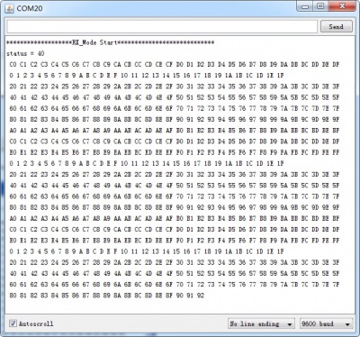
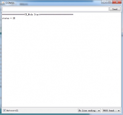
4.Now power on both Arduino , and connect the RX one to PC via USB. Open the IDE serial port monitor , change the baud rate to 9600 bps , and you can see the data that received.
 [
[ 