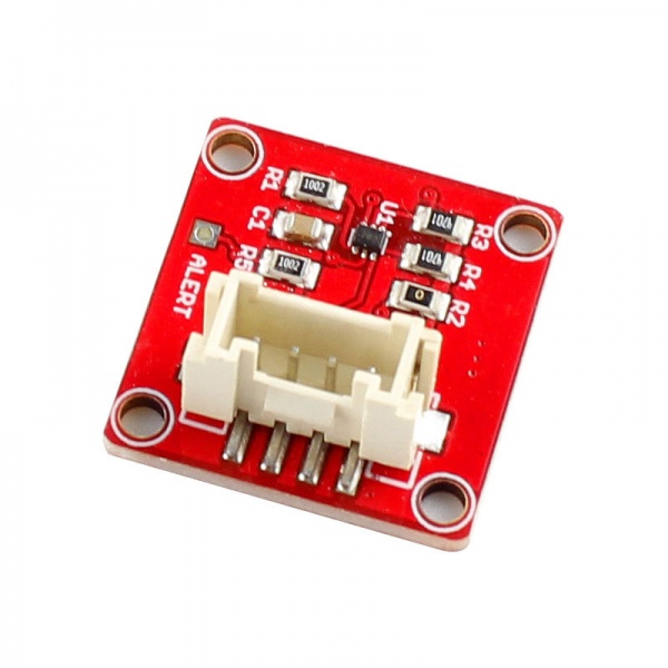
Crowtail- Temperature Sensor TMP102
Description
The TMP102 is a two-wire, serial output temperature sensor. It is also a digital temperature sensor, which has higher stability than analog sensors. While some temperature sensors use an analog voltage to represent the temperature, the TMP102 uses the I2C bus of the Arduino to communicate the temperature. This module is capable of reading temperatures to a resolution of 0.0625℃, and is accurate up to 0.5℃. The breakout has built-in 4.7kΩ pull-up resistors for I2C communications and runs from 1.4V to 3.6V. I2C communication uses an open drain signaling, so there is no need to use level shifting.
Model:CRT00545T
Features
- TINY SOT563 PACKAG
- ACCURACY: 0.5℃(–25℃ to +85℃)
- OW QUIESCENT CURRENT:
- 10μA Active (max)
- 1μA Shutdown (max)
- SUPPLY RANGE: 1.4V to 3.6V
- DIGITAL OUTPUT: Two-Wire Serial Interface
- Temperature scale ratio: 0.0625 ℃
- Accuracy to 0.5 ℃
Specification
Dimensions(mm):20.0(L)x20.0(W)x9.8(H)
| Item | Description |
|---|---|
| LED Control Mode | Digital Pin of Arduino |
| Working Voltage | 5V |
| Supply Mode | Crowtail Interface |
Usage
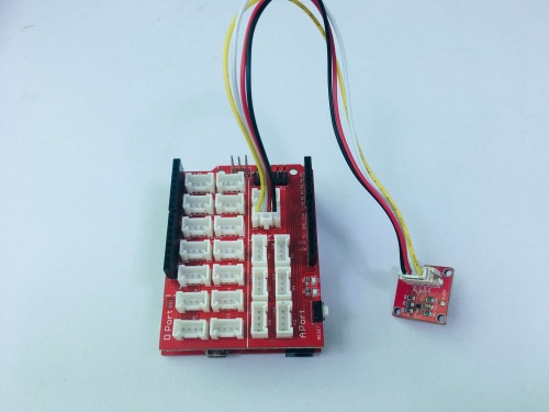
1. Connect the Crowtail-TMP102 to Base Shield's I2C with 4pin Crowtail Cable.
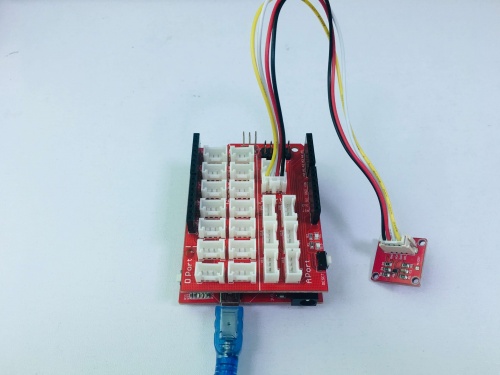
2. Plug it onto the Arduino/Crowduino. Connect the board to PC using USB cable.
3.Download *TMP102for Arduino boards with Temperature Sensor TMP102,Unzip and put it in the libraries file of Arduino IDE by the path: ..\arduino-1.0\libraries;
4.Copy the demo code to your sketch, then upload to Arduino or Crowduino board.
/******************************************************************************
TMP102_example.ino
Example for the TMP102 I2C Temperature Sensor
******************************************************************************/

#include <Wire.h> // Used to establied serial communication on the I2C bus
#include "TMP102.h" // Used to send and recieve specific information from our sensor

// Connections
// VCC = 3.3V
// GND = GND
// SDA = A4
// SCL = A5
const int ALERT_PIN = A3;

TMP102 sensor0(0x48); // Initialize sensor at I2C address 0x48
// Sensor address can be changed with an external jumper to:
// ADD0 - Address
//  VCC - 0x49
//  SDA - 0x4A
//  SCL - 0x4B

void setup() {
  Serial.begin(9600); // Start serial communication at 9600 baud
  pinMode(ALERT_PIN,INPUT);  // Declare alertPin as an input
  sensor0.begin();  // Join I2C bus

  // Initialize sensor0 settings
  // These settings are saved in the sensor, even if it loses power

  // set the number of consecutive faults before triggering alarm.
  // 0-3: 0:1 fault, 1:2 faults, 2:4 faults, 3:6 faults.
  sensor0.setFault(0);  // Trigger alarm immediately

  // set the polarity of the Alarm. (0:Active LOW, 1:Active HIGH).
  sensor0.setAlertPolarity(1); // Active HIGH

  // set the sensor in Comparator Mode (0) or Interrupt Mode (1).
  sensor0.setAlertMode(0); // Comparator Mode.

  // set the Conversion Rate (how quickly the sensor gets a new reading)
  //0-3: 0:0.25Hz, 1:1Hz, 2:4Hz, 3:8Hz
  sensor0.setConversionRate(2);

  //set Extended Mode.
  //0:12-bit Temperature(-55C to +128C) 1:13-bit Temperature(-55C to +150C)
  sensor0.setExtendedMode(0);

  //set T_HIGH, the upper limit to trigger the alert on
//  sensor0.setHighTempF(85.0);  // set T_HIGH in F
  sensor0.setHighTempC(29.4); // set T_HIGH in C

  //set T_LOW, the lower limit to shut turn off the alert
 // sensor0.setLowTempF(84.0);  // set T_LOW in F
  sensor0.setLowTempC(26.67); // set T_LOW in C
}

void loop()
{
  float temperature;
  boolean alertPinState, alertRegisterState;

  // Turn sensor on to start temperature measurement.
  // Current consumtion typically ~10uA.
  sensor0.wakeup();

  // read temperature data
 // temperature = sensor0.readTempF();
  temperature = sensor0.readTempC();

  // Check for Alert
  alertPinState = digitalRead(ALERT_PIN); // read the Alert from pin
  alertRegisterState = sensor0.alert();   // read the Alert from register

  // Place sensor in sleep mode to save power.
  // Current consumtion typically <0.5uA.
  sensor0.sleep();

  // Print temperature and alarm state
  Serial.print("Temperature: ");
  Serial.println(temperature);

 // Serial.print("\tAlert Pin: ");
 // Serial.print(alertPinState);

//  Serial.print("\tAlert Register: ");
//  Serial.println(alertRegisterState);

  delay(1000);  // Wait 1000ms
}
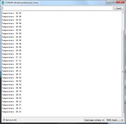
5.After successfull upload the code,you can open the monitor and see the data from Arduino,as below:


