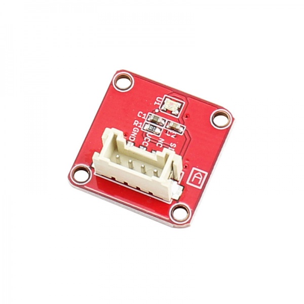
Crowtail- Luminance sensor
Description
The Crowtail- Luminance sensor using APDS-9002 as luminous flux sensor. The APDS-9002 is a analog-output ambient light, It consists of a spectrally suited phototransistor, which peaks in human luminosity curve. Hence, it provides an excellent responsivity that is close to the response of human eyes. The Crowtail- Luminance sensor can reflects the luminous intensity of the environment by the linear output level, and then directly reflect the change of luminous flux.
Model: CRT00549L
Features
- VCC: 2.4-5.5V
- Good output linearity across wide
- Low sensitivity variation across various light sources
- Guaranteed temperature performance: -40°C to 85°C
- Linear output range: 0.0 - 2.3V
- Dimensions(mm):20.0(L)x20.0(W)x9.8(H)
Applications
- Automatic residential and commercial lighting management
- Electronic signs and signals
- Daylight and artificial light exposed devices
Usage
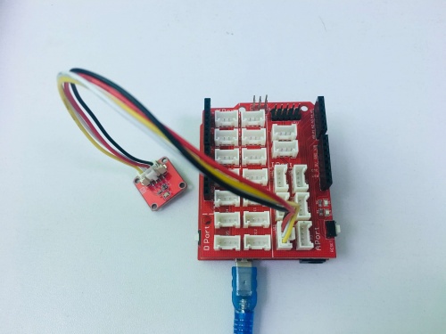
1.Connect the Crowtail luminance sensor to the A0 port of base shield and connect micro USB cable to micro USB port.
2.Copy the demo code to your sketch, then upload to Arduino/Crowduino board.
 float VoutArray[] =  { 0.0011498,  0.0033908,   0.011498, 0.041803,0.15199,     0.53367, 1.3689,   1.9068,  2.3};
float  LuxArray[] =  { 1.0108,     3.1201,  9.8051,   27.43,   69.545,   232.67,  645.11,   73.52,  1000};

void setup() {
    // put your setup code here, to run once:
    Serial.begin(9600);

}

void loop() {
    // put your main code here, to run repeatedly:

    Serial.print("Vout =");
    Serial.print(readAPDS9002Vout(A0));
    Serial.print(" V,Luminance =");
    Serial.print(readLuminance(A0));
    Serial.println("Lux");
    delay(500);
}

float readAPDS9002Vout(uint8_t analogpin)
{
    // MeasuredVout = ADC Value * (Vcc / 1023) * (3 / Vcc)
    // Vout samples are with reference to 3V Vcc
    // The above expression is simplified by cancelling out Vcc
    float MeasuredVout = analogRead(A0) * (3.0 / 1023.0);
    //Above 2.3V , the sensor value is saturated

    return MeasuredVout;

}

float readLuminance(uint8_t analogpin)
{

    // MeasuredVout = ADC Value * (Vcc / 1023) * (3 / Vcc)
    // Vout samples are with reference to 3V Vcc
    // The above expression is simplified by cancelling out Vcc
    float MeasuredVout = analogRead(A0) * (3.0 / 1023.0);
    float Luminance = FmultiMap(MeasuredVout, VoutArray, LuxArray, 9);

    /**************************************************************************

    The Luminance in Lux is calculated based on APDS9002 datasheet -- > Graph 1
    ( Output voltage vs. luminance at different load resistor)
    The load resistor is 1k in this board. Vout is referenced to 3V Vcc.

    The data from the graph is extracted using WebPlotDigitizer
    http://arohatgi.info/WebPlotDigitizer/app/

    VoutArray[] and LuxArray[] are these extracted data. Using MultiMap, the data
    is interpolated to get the Luminance in Lux.

    This implementation uses floating point arithmetic and hence will consume
    more flash, RAM and time.

    The Luminance in Lux is an approximation and depends on the accuracy of
    Graph 1 used.

    ***************************************************************************/

    return Luminance;
}


//This code uses MultiMap implementation from http://playground.arduino.cc/Main/MultiMap

float FmultiMap(float val, float * _in, float * _out, uint8_t size)
{
    // take care the value is within range
    // val = constrain(val, _in[0], _in[size-1]);
    if (val <= _in[0]) return _out[0];
    if (val >= _in[size-1]) return _out[size-1];

    // search right interval
    uint8_t pos = 1;  // _in[0] allready tested
    while(val > _in[pos]) pos++;

    // this will handle all exact "points" in the _in array
    if (val == _in[pos]) return _out[pos];

    // interpolate in the right segment for the rest
    return (val - _in[pos-1]) * (_out[pos] - _out[pos-1]) / (_in[pos] - _in[pos-1]) + _out[pos-1];
}
3. Open the serial monitor.
4.observed the data on the serial monitor, as follows
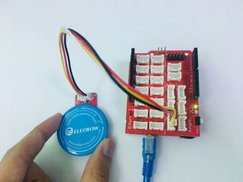
5.Change the brightness around the module.
6.observed the data on the serial monitor, as follows


