Crowbits-Trigger Delay
Description
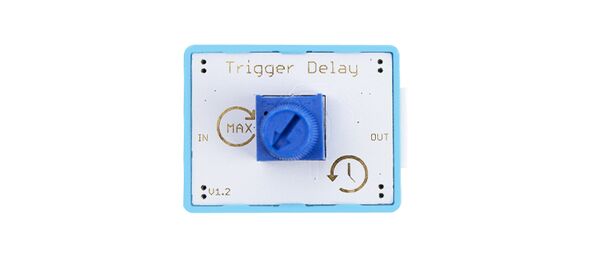
The trigger delay can keep the signal outputs by input module for a certain period of time. The trigger delay is based on an RC circuit, an RC circuit (resistor-capacitor circuit) is an electric circuit composed of resistors and capacitor, which is a way to create a time delay in your circuit. The RC delay circuit works on the principle of the RC charging and discharging. We know that the capacitor is able to store electrical energy they act like small batteries and can store or release the energy as required. When power for the delay module, the capacitor will be charged, and when the voltage of the capacitor reaches a certain value, the capacitor will discharge. The charging and discharging of the energy of a capacitor takes a certain time that we called time delay.
Features
- Single input port.
- Single output port.
- Output indicator.
Specification
- Operating Voltage: 3.3V DC
- Supply mode: Crowbits Power Module
- Dimensions: 31.5(L)*24.5(W)*13(H) mm
Usage
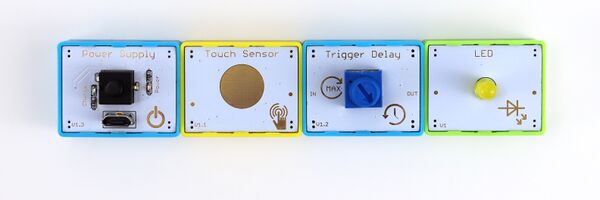
1)You also need a power module, such as Crowbits-Power Supply; An input module, such as Crowbits-Touch Sensor and Crowbits-Trigger delay; An extension module, such as Crowbits-LED.
2)The connection mode is shown in the figure, but the signal feet of the input module and the output module must be connected.
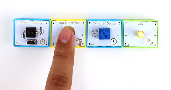
3)Then, press the Touch Sensor. the LED light.
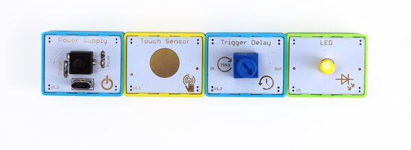
4)Let go of Touch Sensor,the LED slowly goes out.
5)Rotate the knob to adjust the speed of the LED light off.


