ThinkNode M2 Meshtastic (LoRa) Signal Transceiver Powered By ESP32-S3
Description
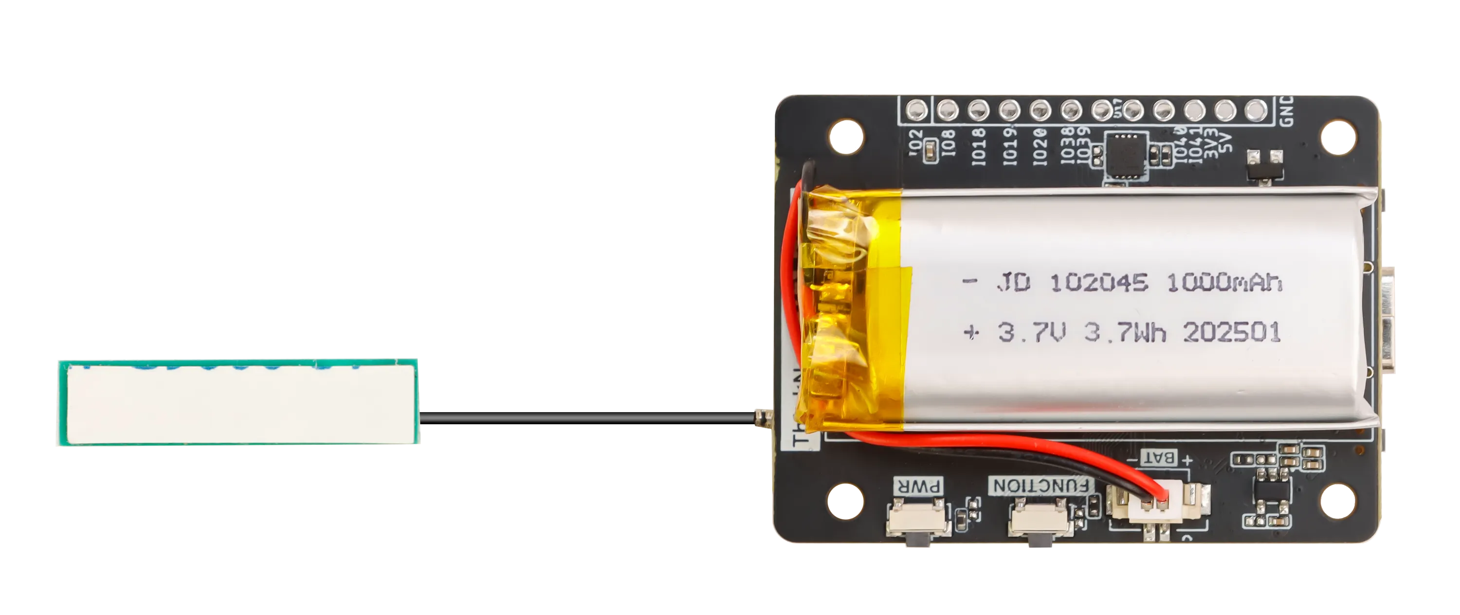
Elecrow ThinkNode-M2 is a high-performance LoRa signal transceiver. It uses the ESP32-S3 module as the main processor and supports Bluetooth. Users can easily configure and monitor the device through their mobile phones. M2 is pre-installed with Meshtastic firmware and equipped with an SX1262 wireless chip, which can efficiently send and receive LoRa signals to ensure the reliability and stability of communication. In addition, M2 is perfectly compatible with the official Meshtastic App. Users can use the App to implement parameter configuration, message communication, map and location sharing, network status monitoring, data recording and export, and custom settings.
The built-in 1**.3-inch OLED display** can display data and device status in real-time, which is convenient for users to view at any time. Built-in 1000mAh rechargeable battery supports long-term outdoor use. The LoRa antenna supports multiple frequency options to optimize communication performance further. The device adopts a modular design to facilitate embedded integration and custom development.
With integrated LoRa communication technology, ThinkNode-M2 achieves efficient connection and data exchange between devices. Whether in remote areas where cellular networks are not available or in emergencies, M2 can be used as an independent communication tool to provide critical safety assurance. It is also suitable for low-cost information exchange and transmission and reception solutions between communities to meet diverse communication needs.
Self-developed by Elecrow with exclusive design.
For customized requirements (based on MOQ), please contact us at service@elecrow.com.
Model CIL13002M
_Power_By_NRF52840/ThinkNode-M2-1.webp)
Features
- Thinknode M2’s firmware is adapted to the Meshtastic protocol, it can realize efficient and stable transmission and reception of Lora signals;
- 1.3-inch OLED display screen for real-time viewing of data and device status;
- Built-in 1000mAh lithium battery, it can Meet the needs of long-term outdoor use;
- Adopts modular style, suitable for embedded solution product design;
- Compatible with the Meshtatic official App. Users can use the App to configure and manage parameters of the M1 device, communicate messages, share maps and locations, monitor network status, record and export data, customize settings, etc.
- Compact size, easy to carry and durable;
- External LoRa antenna ensures the stability and efficiency of signal transmission;
Specification
| Main Processor(ESP32-S3 Module) | |
|---|---|
| CPU/SoC | Equipped with high-performance Xtensa 32-bit LX7 dual-core processor, with a main frequency of up to 240MHz |
| System Memory | 512KB SRAM、8M PSRAM |
| Storage | 4M Flash,384KB ROM |
| Firmware | Meshtastic firmware is fully compatible, and the signal is transmitted in LoRa mode |
| Display | |
| Size | 1.3 inch |
| Display Materials | OLED |
| Resolution | 128*64 |
| Driver Chip | SH1106 |
| Wireless Communication | |
| WiFi | Support 802.11a/b/g/n, 2.4GHz |
| Bluetooth | Bluetooth Low Energy and Bluetooth 5.0 |
| LoRa | SX1262 LoRa Transceiver、US 915MHz / EU 868MHz |
| Hardware | |
| Interface | Type-C Interface, IPEX antenna connector (internal), battery connector (internal) |
| Function | LCD display, USB2.0, power management, USB to UART, buzzer, etc. |
| Button | Power button, Function button, Reset button, BOOT button |
| LED Indicator | Power indicator, charging indicator |
| Other | |
| Power Input | 5V/1A, supports USB or lithium battery power supply |
| Power consumption | The maximum working power consumption is about 217mA, and the low power consumption is about 136mA (screen-off state) |
| Operating Temperature | -10~50°C |
| Storage Temperature | -20~60 °C |
| Relative humidity | 10%-95%, @ 40°C (non-condensing) |
| Size | With Case:88.4*46*23mm;Without Case:51.5*37*9.5mm |
| Shell | ABS Plastic |
| Net weight | 30g(Without case);50g(With case) |
PWR indicator function
| Serial No. | Name | Signal | Master Signal | Color | Description | |
|---|---|---|---|---|---|---|
| 1 | Power indicator | PWR | IO1_LEDIO6CHGLED | IO1 | red | Ø Device powered on, indicator light is always on; Ø With lithium battery charging, indicator light (fast blinking); charging is complete, indicator light is always on; Ø Low battery slow blinking; Ø Buzzer open alarm, indicator light blinking |
Interface/Keypad Functions
_Power_By_NRF52840/ThinkNode-M2-g.webp)
| Serial No. | Name | Signal | Master Signal | Functions | |
|---|---|---|---|---|---|
| 1 | PWR Button | PWR | P3.3_IO4_POWER | IO4 | Short press to turn on/long press 3s to turn off power on, short press to rest the screen |
| 2 | FUNCTION Button | FUNCTION | IO47_FUNCTION | IO47 | Ø Single-click: scroll down function, switch screen display page Ø Double-click: send a temporary PING of the device location to the network Ø Triple-click: trigger the SOS alarm signal (three long and three short), the buzzer sounds, and the indicator light flashes |
| 3 | BAT connector | BAT | / | / | Access to batteries to power the board |
| 4 | Type-C connector | USB-IN | ESP32_TXD0ESP32_RXD0 | IO43IO44 | Used for programming and debugging the ESP32 S3 and can also charge the battery with a charging current of 1A |
| 5 | screen interface | / | IO46SCLSDA | IO46IO15_SCLIO16_SDA | IO46 control screen switches IO15_SCL and IO16_SDA control the screen display |
| 6 | RESET Button | RESET | EN | EN | Reset ESP32 S3 |
| 7 | BOOT Button | BOOT | BOOT | IO0 | For ESP32 S3 in burn-in mode |
| 8 | LORA Antenna Interface | LORA_ANT | / | / | Access to 868/915 antenna |
GPIO interface function
| Serial No. | Pin | Master Signal | Functions | |
|---|---|---|---|---|
| 1 | IO2 | IO2 | IO2 | RTC_GPIO2, GPIO2, TOUCH2, ADC1_CH1 |
| 2 | IO8 | IO8 | IO8 | RTC_GPIO8, GPIO8, TOUCH8, ADC1_CH7, SUBSPICS1 |
| 3 | IO18 | IO18 | IO18 | RTC_GPIO18, GPIO18, U1RXD, ADC2_CH7, CLK_OUT3 |
| 4 | IO19 | IO19 | IO19 | RTC_GPIO19, GPIO19, U1RTS, ADC2_CH8, CLK_OUT2, USB_D |
| 5 | IO20 | IO20 | IO20 | RTC_GPIO20, GPIO20, U1CTS, ADC2_CH9, CLK_OUT1, USB_D+ |
| 6 | IO38 | IO38 | IO38 | GPIO38, FSPIWP, SUBSPIWP |
| 7 | IO39 | IO39 | IO39 | MTCK, GPIO39, CLK_OUT3, SUBSPICS1 |
| 8 | IO40 | IO40 | IO40 | MTDO, GPIO40, CLK_OUT2 |
| 9 | IO41 | IO41 | IO41 | MTDI, GPIO41, CLK_OUT1 |
| 10 | 3V3 | 3V3 | / | 3.3V供电 |
| 11 | 5V | VBUS | / | 5V供电 |
| 12 | GND | GND | / | GND |
SX1262 Pin
| Serial No. | Pin | Type | Master Signal | Description |
|---|---|---|---|---|
| 1 | SX1262_CS | I/O | IO10 | Used to select the SX1262 chip for communication. When this pin is pulled low, the SX1262 chip is selected for SPI communication. |
| 2 | SX1262_SCK | I/O | IO12 | Clock line for SPI interface for synchronized data transfer |
| 3 | SX1262_MOSI | O | IO11 | The master device data output line of the SPI interface is used to send data from the microcontroller to the SX1262. |
| 4 | SX1262_MISO | I | IO13 | The master device data input line of the SPI interface is used to receive data from the SX1262 to the microcontroller. |
| 5 | SX1262_RESET | I/O | IO21 | Reset SX1262 chip. When this pin is pulled low, the SX1262 chip resets. |
| 6 | SX1262_BUSY | I/O | IO14 | Indicates if the SX1262 chip is busy. When this pin is high, it indicates that the chip is busy. |
| 7 | SX1262_DIO1 | I/O | IO3 | Digital Input/Output Pins |
| 8 | SX1262_DIO2 | I/O | / | DIO2 connects to RF_SW, which is set as the control pin of RF switch to control the receiving and transmitting of RF signals |
| 9 | SX1262_DIO3 | P | / | DIO3 for TCXO power supply |
Usage
Prepare two mobile phones with Meshtastic APP installed and two thinknode M5\M1\M2 devices.
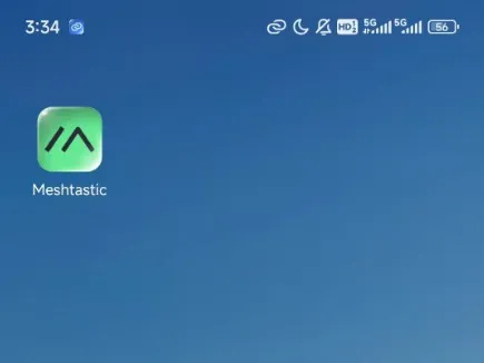
First go to the app store to download and install the Meshtastic APP
Same settings on the receiving side as on the transmitting side
After opening the app, select the top far right and click on Configuration, click on the + in the bottom right corner to find the Meshtastic Bluetooth device.
_Power_By_NRF52840/ThinkNode-M2.webp)
_Power_By_NRF52840/ThinkNode-M2-2.webp)
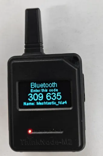
2)When the Meshtastic_xxxx device is searched, tap to enter pairing mode.
_Power_By_NRF52840/ThinkNode-M2-3.webp)
3)After successful Bluetooth pairing, you need to select a new region at the region again.
_Power_By_NRF52840/ThinkNode-M2-6.webp)
4) Set lora frequency, click on the upper right corner of the three points, click on “Radio configurtion”, and then click on “Lora”, scroll down to the ‘Add’ column, in the “Override frequency (Mhz)” at the corresponding frequency written.
_Power_By_NRF52840/lora setting-1.webp)
_Power_By_NRF52840/lora setting-2.webp)
_Power_By_NRF52840/lora setting-3.webp)
5)If two devices want to communicate, they need to join to the same channel, this time you need to select the fourth of the five options above, the other end of the phone needs to join to the same channel by scanning the code or entering the link, the channel can be customized name and so on.
_Power_By_NRF52840/ThinkNode-M2-7.webp)
6)After joining, the two devices can now chat in the first screen by selecting Group Chat.
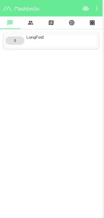
Mutual Messaging Interface.
A-end:
_Power_By_NRF52840/ThinkNode-A-end-5.webp)
B-end:
_Power_By_NRF52840/ThinkNode-B-end.webp)
Same settings on the receiving side as on the transmitting side
1)Open the app, tap Bluetooth on the home page and see the device you want to connect. Click on Pairing.
_Power_By_NRF52840/ios-1.webp)
_Power_By_NRF52840/ios-2.webp)
2)When the Meshtastic_xxxx device is searched, tap to enter pairing mode.
_Power_By_NRF52840/ThinkNode-M2-4.webp)
_Power_By_NRF52840/ios-3.webp)
3)After successful Bluetooth pairing, You need to go to Settings and click on Lora Settings.
_Power_By_NRF52840/ios-4.webp)
4) Set lora Region. and then scroll down to set the frequency. consistent with the previous settings for the region. Finally, check ignore MQTT and save.
_Power_By_NRF52840/ios-5.webp)
_Power_By_NRF52840/ios-7.webp)
_Power_By_NRF52840/ios-6.webp)
_Power_By_NRF52840/ios-8.webp)
_Power_By_NRF52840/ios-9.webp)
5)Go to the information page, select a channel and a QR code will appear, use another device to scan this QR code to enter.
_Power_By_NRF52840/ios-10.webp)
_Power_By_NRF52840/ios-11.webp)
6)Join and start sending or receiving messages.
_Power_By_NRF52840/ios-12.webp)
Github Resources
ThinkNode-M2-Meshtastic-LoRa-Signal-Transceiver-Powered
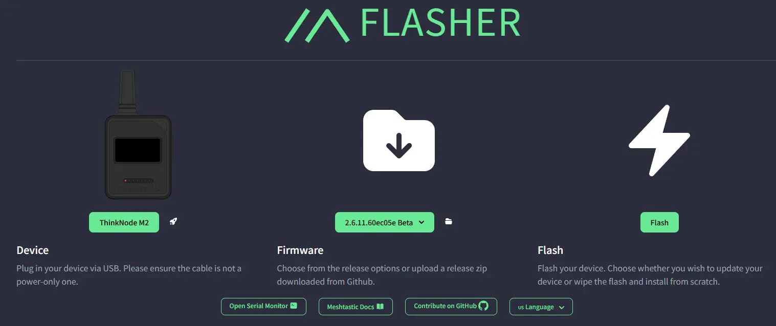
Burning Firmware
ClickMeshtastic firmware
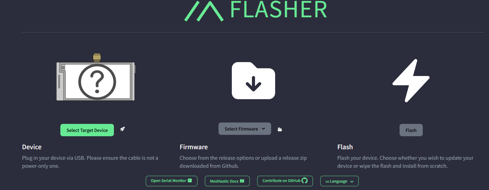
1, Select the corresponding firmware.
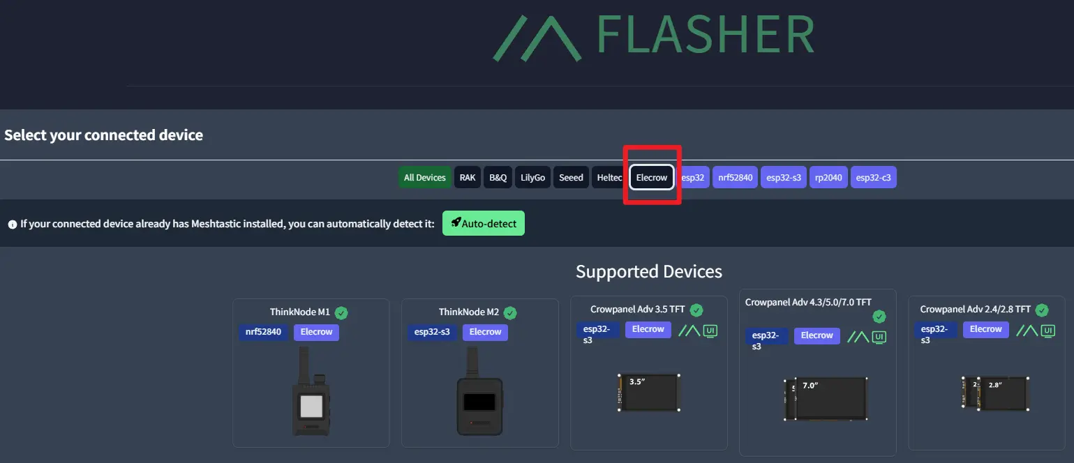
2, follow the steps to download the firmware.
How to buy
Please visit this page to purchase Thinknode M2.
Support
If you have any problem about how to use it, you can connect to us at the bottom-right of bazzer or contact to techsupport@elecrow.com to get technology support.