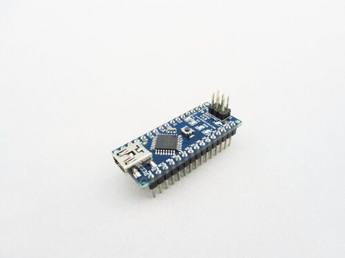
Nano 168(Arduino Compatible)
Description
The Nano 168 is a small, complete, and breadboard-friendly board based on the ATmega328 (Arduino Nano 3.0) or ATmega168 (Arduino Nano 2.x).It have an integrated on-board USB. As the function, It has almost all the analog and digital pins that the UNO or Duemilanove has and the same function as Duemilanove or UNO except the Microcontroller is using Mega 168. Its price is cheaper than Nano 328(Arduino compatible), the only difference of them is the MicroController, one using Mega 168 and the other one using Mega 328. This Nano 168 can give more selections for your project. With the smaller and portable package. This Nano 168 can go with the IO Shield for Arduino Nano, it would be more friendly and convenient for users to enter the Arduino world and make use of Arduino to make their dream into reality.
As an upgrade version of Arduino Nano, the Nano 168 is 100% compatible to Arduino Nano and its shield and IDEs. On the hardware part, remarkable changes are taken to improve the flexibility and user experience.
Model: MCA03168A
Features
- Power OK red LED, Green (TX), green (RX) and green (L) LED
- Upgraded 5V voltage sourcing, more powerful drive capability
- Mini-B USB for programming and serial monitor, TX&RX breakout for application as USB-UART convertor
- Surface-Mount ICSP header
- Standard 2.54mm spacing DIP (breadboard friendly)
Specification
| Item | Value |
|---|---|
| Micro controller | ATmega168 |
| Operating Voltage(logic level) | 5V |
| Input Voltage(recommended) | 7-12 V |
| Input Voltage(limits) | 6-20 V |
| Digital I/O Pins | 14 (of which 6 provide PWM output) |
| Analog Input Pins | 8 |
| DC Current per I/O Pin | 40 mA |
| Flash Memory | 16 KB (ATmega168) or 32 KB (ATmega328) of which 2 KB used by bootloader |
| SRAM | 1 KB (ATmega168) or 2 KB (ATmega328) |
| EEPROM | 512 bytes (ATmega168) or 1 KB (ATmega328) |
| Clock Speed | 16 MHz |
| Dimension | 0.73" x 1.70" |
Power
The Arduino Nano can be powered via the Mini-B USB connection, 6-20V unregulated external power supply (pin 30), or 5V regulated external power supply (pin 27). The power source is automatically selected to the highest voltage source.
The FTDI FT232RL chip on the Nano is only powered if the board is being powered over USB. As a result, when running on external (non-USB) power, the 3.3V output (which is supplied by the FTDI chip) is not available and the RX and TX LEDs will flicker if digital pins 0 or 1 are high.
Memory
The ATmega168 has 16 KB of flash memory for storing code (of which 2 KB is used for the bootloader); the ATmega328 has 32 KB, (also with 2 KB used for the bootloader). The ATmega168 has 1 KB of SRAM and 512 bytes of EEPROM (which can be read and written with the EEPROM library); the ATmega328 has 2 KB of SRAM and 1 KB of EEPROM.
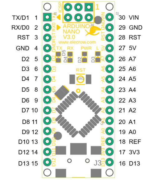
Pin Layout
| Pin No. | Pin Name | Type | Description |
|---|---|---|---|
| 1-2, 5-16 | D0-D13 | I/O | Digital input/output port 0 to 13 |
| 3, 28 | RST | Input | Reset(active low) |
| 4,29 | GND | PWR | Supply ground |
| 17 | 3V3 | Output | +3.3V output(from FTDI) |
| 18 | AREF | Input | ADC reference |
| 19-26 | A0-A7 | Input | Analog input channel 0 to 7 |
| 27 | +5V | Output or Input | +5V output(from on-board regulator) or +5V input(from external power supply) |
| 30 | VIN | PWR | Supply voltage |
Platforms Supported
| Arduino |
|---|
 |
Usage
Hardware
STEP1 Prepare the below stuffs:
| Nano 168 |
|---|
 |
| Get one now |
STEP2 Connect Nano 168 to PC via a USB cable.
Software
STEP1 Download program files Nano_test.zip
STEP2 Configure controller board&communication port
On top of the Arduino IDE, click “Tools>Board>” and select “ATmega168” from the available options 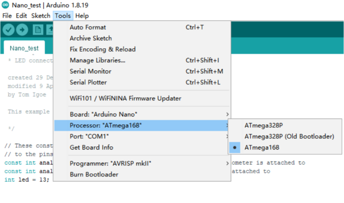
Select the COM port that indicates Arduino Uno. Please note that the actual numbers after the “COM” word will vary from computer to computer, so they could be different from the ones shown in the figure. 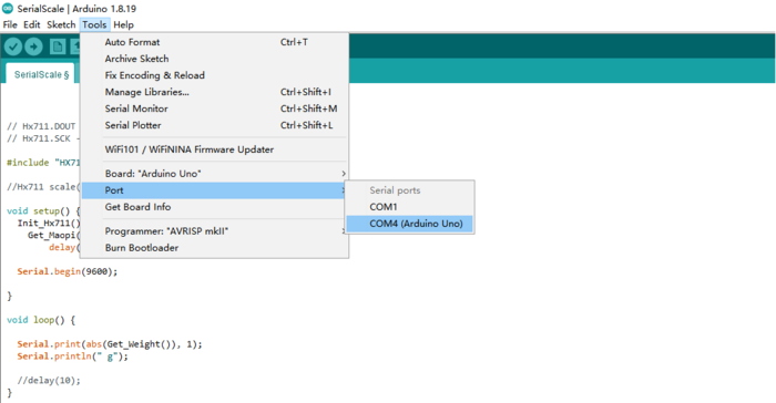
STEP 3.Open the program in the Arduino IDE
/*
  Analog input, analog output, serial output

 Reads an analog input pin, maps the result to a range from 0 to 255
 and uses the result to set the pulsewidth modulation (PWM) of an output pin.
 Also prints the results to the serial monitor.

 The circuit:
 * potentiometer connected to analog pin 0.
   Center pin of the potentiometer goes to the analog pin.
   side pins of the potentiometer go to +5V and ground
 * LED connected from digital pin 9 to ground

 created 29 Dec. 2008
 modified 9 Apr 2012
 by Tom Igoe

 This example code is in the public domain.

 */

// These constants won't change.  They're used to give names
// to the pins used:
const int analogInPin = A0;  // Analog input pin that the potentiometer is attached to
const int analogOutPin = 9; // Analog output pin that the LED is attached to
int led = 13;
int sensorValue = 0;        // value read from the pot
int outputValue = 0;        // value output to the PWM (analog out)

void setup() {
  // initialize serial communications at 9600 bps:
  Serial.begin(9600);
    pinMode(led, OUTPUT);
}

void loop() {
  // read the analog in value:
  sensorValue = analogRead(analogInPin);
  // map it to the range of the analog out:
  outputValue = map(sensorValue, 0, 1023, 0, 255);
  // change the analog out value:
  analogWrite(analogOutPin, outputValue);

  // print the results to the serial monitor:
  Serial.print("sensor = " );
  Serial.print(sensorValue);
  Serial.print("\t output = ");
  Serial.println(outputValue);

  // wait 2 milliseconds before the next loop
  // for the analog-to-digital converter to settle
  // after the last reading:
 // delay(2);
   digitalWrite(led, HIGH);   // turn the LED on (HIGH is the voltage level)
  delay(500);               // wait for a second
  digitalWrite(led, LOW);    // turn the LED off by making the voltage LOW
  delay(500);               // wait for a second
}
STEP4 Click the  to upload the code to the Arduino Nano
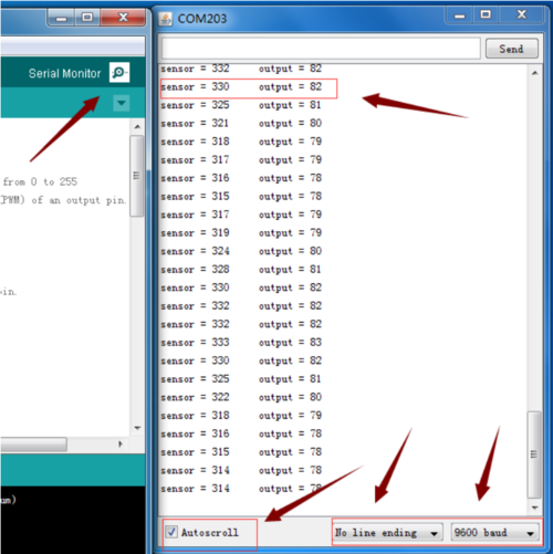
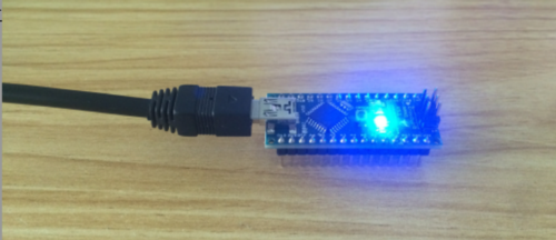
STEP5 After downloading the test program, open the Serial Monitor, which shows output, L (yellow) and TX (green) LED lights on the board flashing, PWR (blue) LED lights on long
FAQs
You can list you question here or contact with techsupport@elecrow.com for technology support.
