8-Channel EL Shield
Description
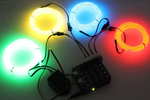
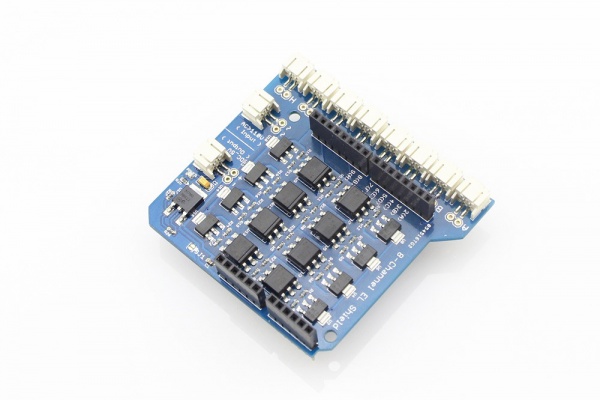
EL wire is flexible plastic cord that glows brightly when high-voltage AC is applied to it. It’s available in numerous colors with cool, and requires very little current, but it can be difficult to work with because of the high-voltage requirements. The Elecrow EL Shield enables you to implement up to 8 channels of EL wires or tapes in to your project and gives you solution to control the EL modules. With Arduino or Crowduino, You will be able to control 8 EL devices simultaneously and separately. The controlling method is as simple as controlling an LED. Driven by PWM, it can create a colorful and florid effect by controlling each EL wire according to your own programs.
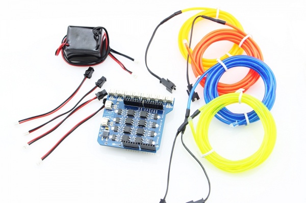
This Shield comes with 4 pics of EL wire adaptors to help you connect the standard EL wires to this Shield. Of course you can purchase more to control up to 8 channels. Please also notice that a 5V invertor is needed for this EL shield.Besides, there is also the 8-Channel EL Shield Kit which includes all the modules you need for a EL wire project.
Model: AS0008EL
Featrues
- 8 Channels, with Eight opto-isolated, zero-crossing control channels;
- Control EL as easy as turning a LED on and off;
- Compatible with 5V or 3.3V Arduinos
- Dimensions(mm):72.5(L)x66.0(W)x23.5(H)
Pin Allocatior
| PIN | EL Channel to Control |
|---|---|
| D2 | EL Channel A |
| D3 | EL Channel B |
| D4 | EL Channel C |
| D5 | EL Channel D |
| D6 | EL Channel E |
| D7 | EL Channel F |
| D8 | EL Channel G |
| D9 | EL Channel H |
Usage
1.Connect the EL wires to EL Shield via the Adaptor
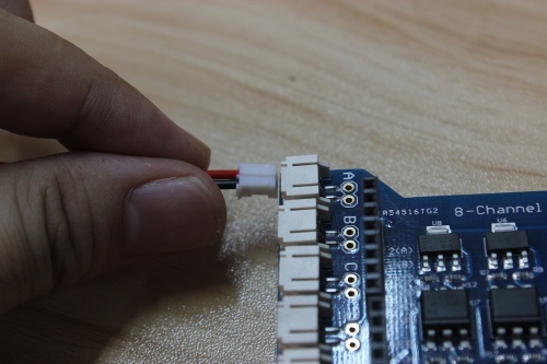
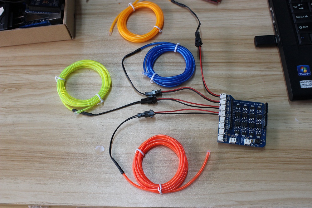
As the standard EL wires or tapes use the connectors that can not be pluged into a PCBA, we provide the Special wire adaptors to help uses connect the EL modules to the EL Shiled. 4 pcs of adaptors are packaged in the EL Shield or EL Shield Kit. connect the EL wires to EL Shiled as below:
2.Connect the inverter to EL Shield
The EL modules needs a driver voltage more than 110V, AC. The Elecrow customized inverter can convert the 5V-DC input to AC,110~220V, can drive a max of 15m EL wires. connecthe the inverter to EL Shield as below:
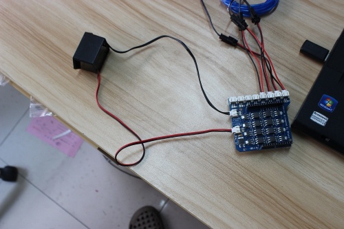
Note that the input wire of the inverter is red/white, which need to be inserted into the DC_5V terminal of EL Shield, and the output wire(black) of the inverter need to be inserted into the AC>110V terminal.
3.Programing on Crowduino
Plug the EL Shield on to Crowduino, then you can begin to programming the Crowduino to control EL wires. Progrmming to control the EL wires would be as easy as control a LED, you can use the digitalwrite() to control the EL wires on&off, or the analogwrite() to generate PWM to control the lightness.
void setup(){
 for(int i = 2; i<10; i++)
 {
  pinMode(i, OUTPUT);
 }
}

void setEL(int ch) // set a certain EL on
{
  for(int i = 2; i<10; i++) // all on
 digitalWrite(i, HIGH);
 delay(1000);
 for(int i = 2; i<10; i++) // all off
 digitalWrite(i, LOW);
  for(int i = 2; i<10; i++) //
 {
  digitalWrite(i, HIGH);
  delay(200);
  digitalWrite(i, LOW);
 }
 }

int count = 0;

void loop()
{
 setEL(count%4 + 1);
 delay(200);
 if(count++ == 1000)
 {
  count = 0;
 }
}
4.Power On to Start
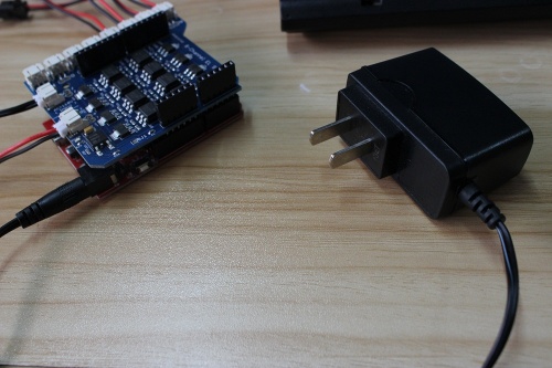
After uploading the sketch to Crowduino, Power the Crowduino&Arduino with a 6.5~9 V DC supply via the DC jack, to enable the EL wires blink
