Dual Channel H-Bridge Motor Shield
Description
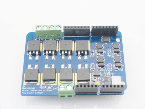
The Dual Channel H-Bridge Motor Shield is composed of 2 discrete MOSFET H-bridge, designed to drive two DC motor with max current 8A. It is made up of 8 N-channel MOSFET IRF3205S and 4 pcs of half bridge motor controller IR2104, to build 2 H-bridge. With this shield and the Arduino board, users can control and drive motors with a max current 8A@ 22V. The universal 7.4~11.1V lipo battery that are popular used in the remote car and model airplane can be applied as well.
The H-Bridge Motor Shield can be controlled by simply applying logic 0 or 1 to the direction pins for that motor and a PWM signal to the speed pin. In this way, speed and direction of two separate motors can be controlled independently. Note that the PWM signal on the P_1 and P_2 can be 0~99%, but 100% high signal (logic 1) not works because of the motor controller IR2104 boost circuit.
Model: ACS70028DH
Features
- Uses the IRF3205S MOSFET, which support max current up to 110A
- Uses Half bridge motor controller IR2104, to avoid H-bridge shortage.
- 2 Channels
Specifications
| Item | Min | Typical | Max | Unit |
|---|---|---|---|---|
| Logic Control Voltage | 4.5 | 5 | 5.5 | V |
| Motor Supply Voltage | 6 | / | 22 | V |
| Output Voltage | 0 | / | Vinput -1 | V |
| Output Current( For Each Channel) | / | / | 8000 | mA |
| Output Duty range | 0%~99% | / | ||
| Dimension | 77.0(L)x55.0(W)x23.5(H) | mm | ||
H-Bridge Introduction
What is H-Bridge?
H Bridge configuration is commonly used in electrical applications where the load needs to be driven in either direction. Sometimes it is called a "full bridge", the H-bridge is so named because it has four switching elements at the "corners" of the H and the motor forms the cross bar. The basic bridge is shown in the figure to the right. A typical H-Bridge structure is shown below:
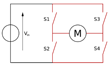
The current flows through the load M – Motor in one direction when S1 and S4 switches are closed and current flows in the other direction when S2 and S3 switches are closed. Controller these switches on/off would be surly control the current directly, thus to control the motor rotation. As you see, 4 switches would be needed for a H-bridge, that is way you can see 8 Mosfet on the elecrow dual channel h-bridge motor shield.
Why H-Bridge Shield But Not Driver IC Solution Such As L298?
Actually, there are many Integrated motor driver IC such L298 that maybe easy to use and cheaper, but if your application need larger drive current, for example, 5A current to drive quad-rotor, using discrete device to build H-bridge would be a better solution, they support larger current with lower heat dissipation and higher switching speed. The popular used motor driver IC L298P or L298N can only support a max current of 2A, with terrible heat dissipation that may burn you, but this Elecrow Dual Channel h-bridge Motor Shield would support a minimum of current 8A, with a little heat dissipation, the peak current can be even to 15A.
Actually, if i have a more powerful power resource to test this shield, i believe it would supply a larger driver current.
Interface Function
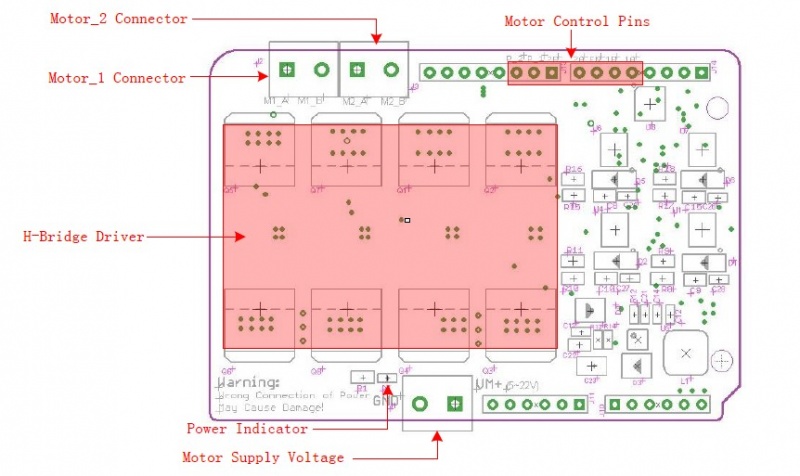
Motor Supply Voltage: ------> External Power supply for the Motor Shield, Could be 6~22V depending on the motor you used
Power Indicator: ------> LED indicator for the external power supply.
H-Bridge Driver: ------> 8 High-power MOSFET to build H-Bridge.
Motor_1&2 Connector: ------> Connect your motors here, the H-Bridge motor shield can drive 2 motors simultaneously, of course it can also drive a 4-wire stepper.
Motor Control Pins: ------> Arduino pins used to control the motor direction&speed as belows:
| Motor | Pin Name | Arduino pin | Description |
| Motor_1 | 1A | D4 | D4=0,D5=1 -> clockwise; D4=1,D5=0 -> anticlockwise; |
| 1B | D5 | ||
| P_1 | D9 | Motor_1 speed control, duty can be 0%~99% | |
| Motor_2 | 2A | D7 | D7=0,D8=1 -> clockwise; D7=1,D8=0 -> anticlockwise; |
| 2B | D8 | ||
| P_2 | D10 | Motor_2 speed control, duty can be 0%~99% | |
| Motor_1 and Motor_2 | EN | D6 | Motor Shield Output Enable, Should be set to "1" while working |
Usage
The Dual-Channel H-Bridge Motor Shield is easy to use, plug on the motor shield onto Croduino, connect your motors to motor shield via the motor_1 and motor_2 connect, and then connect the Crowduino to PC via USB.
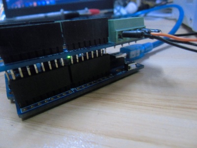
And then, connect the the power supply for motors, via the power supply screws.
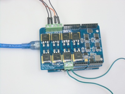
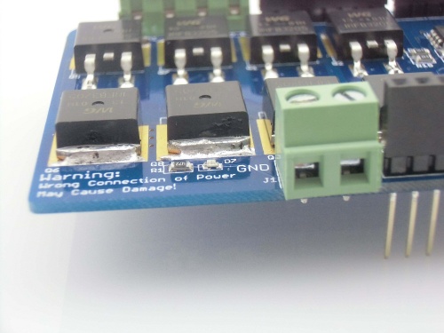
Important, be careful about the polarity of the power supply as the wrong connection may destroy the motor controller especilly when using high voltage power supply. 
The Arduino control the 2 motors as belows:
void setup() {
 // Motor_1 controll pin initiate;
 pinMode(4, OUTPUT);
 pinMode(5, OUTPUT);
 pinMode(9, OUTPUT); // Speed control

 // Motor_2 controll pin initiate;
 pinMode(7, OUTPUT);
 pinMode(8, OUTPUT);
 pinMode(10, OUTPUT);  // Speed control

 //Enable the Motor Shield output;
 pinMode(6, OUTPUT);
 digitalWrite(6, HIGH);
}
void loop() {

   analogWrite(9,230);    // set the motor_1 speed ;
   digitalWrite(4, HIGH);
   digitalWrite(5, LOW);  // Set the rotation of motor_1

   analogWrite(10,50);    // set the motor_2 speed ;
   digitalWrite(7, HIGH);
   digitalWrite(8, LOW);  // Set the rotation of motor_2

  delay(5000);               // wait for a 5 seconds
  // And we change the motor speed and  rotation direction
    analogWrite(9,100);    // set the motor_1 speed to 100 ;
   digitalWrite(4, LOW);
   digitalWrite(5, HIGH);  // Set the rotation of motor_1

   analogWrite(10,150);    // set the motor_2 speed to 150
   digitalWrite(7, LOW);
   digitalWrite(8, HIGH);  // Set the rotation of motor_2
   delay(5000) ;              // wait for a 5 seconds
}
