Serial WIFI Transceiver Module ESP8266
Description
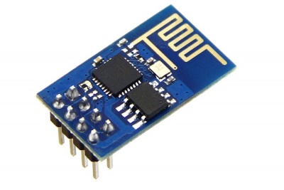
This serial WiFi transceiver module is based on ESP8266 SoC.. ESP8266 is a highly integrated chip that has Integrated TCP/IP protocol stack. It offers a complete and self-contained Wi-Fi networking solution, allowing it to either host the application or to offload all Wi-Fi networking functions from another application processor.
Besides, ESP8266 has powerful on-board processing and storage capabilities that allow it to be integrated with the sensors and other application specific devices through its GPIOs with minimal development up-front and minimal loading during runtime. Its high degree of on-chip integration allows for minimal external circuitry, and the entire solution, including front-end module, is designed to occupy minimal PCB area.
Model:WWI8266ESP
Feature
- 3SDIO 2.0, SPI, UART
- 32-pin QFN package
- Integrated RF switch, balun, 24dBm PA, DCXO, and PMU
- Integrated RISC processor, on-chip memory and external memory interfaces
- Integrated MAC/baseband processors
- Quality of Service management
- I2S interface for high fidelity audio applications
- On-chip low-dropout linear regulators for all internal supplies
- Proprietary spurious-free clock generation architecture
- Integrated WEP, TKIP, AES, and WAPI engines
Specification
- 802.11 b/g/n
- Wi-Fi Direct (P2P), soft-AP
- Integrated TCP/IP protocol stack
- Integrated TR switch, balun, LNA, power amplifier and matching network
- Integrated PLLs, regulators, DCXO and power management units
- +19.5dBm output power in 802.11b mode
- Power down leakage current of <10uA
- Integrated low power 32-bit CPU could be used as application processor
- SDIO 1.½.0, SPI, UART
- STBC, 1×1 MIMO, 2×1 MIMO
- A-MPDU & A-MSDU aggregation & 0.4ms guard interval
- Wake up and transmit packets in < 2ms
- Standby power consumption of < 1.0mW (DTIM3)
Interface Function
AT Commands
Format
- Baud rate at 115200
- x is the commands
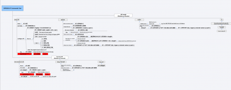
(Click the picture to zoom in)
| Set | Inquiry | Test | Execute |
|---|---|---|---|
| AT+<x>=<…> | AT+<x>? | AT+<x>=? | AT+<x> |
| AT+CWMODE=<mode> | AT+CWMODE? | AT+CWMODE=? | - |
| Set the network mode | Check current mode | Return which modes supported | - |
Commands
- carefully there are must be no any spaces between the " and IP address or port
| Commands | Description | Type | Set/Execute | Inquiry | test | Parameters and Examples |
|---|---|---|---|---|---|---|
| AT | general test | basic | - | - | - | - |
| AT+RST | restart the module | basic | - | - | - | - |
| AT+GMR | check firmware version | basic | - | - | - | - |
| AT+CWMODE | wifi mode | wifi | AT+CWMODE=<mode> | AT+CWMODE? | AT+CWMODE=? | 1= Sta, 2= AP, 3=both, Sta is the default mode of router, AP is a normal mode for devices |
| AT+CWJAP | join the AP | wifi | AT+ CWJAP =<ssid>,< pwd > | AT+ CWJAP? | - | ssid = ssid, pwd = wifi password |
| AT+CWLAP | list the AP | wifi | AT+CWLAP | |||
| AT+CWQAP | quit the AP | wifi | AT+CWQAP | - | AT+CWQAP=? | |
| AT+ CWSAP | set the parameters of AP | wifi | AT+ CWSAP= <ssid>,<pwd>,<chl>, <ecn> | AT+ CWSAP? | ssid, pwd, chl = channel, ecn = encryption; eg. Connect to your router: AT+CWJAP="www.electrodragon.com","helloworld"; and check if connected: AT+CWJAP? | |
| AT+CWLIF | check join devices' IP | wifi | AT+CWLIF | - | - | |
| AT+ CIPSTATUS | get the connection status | TCP/IP | AT+ CIPSTATUS | <id>,<type>,<addr>,<port>,<tetype>= client or server mode | ||
| AT+CIPSTART | set up TCP or UDP connection | TCP/IP | 1)single connection (+CIPMUX=0) AT+CIPSTART= <type>,<addr>,<port>; 2) multiple connection (+CIPMUX=1) AT+CIPSTART= <id><type>,<addr>, <port> | - | AT+CIPSTART=? | id = 0-4, type = TCP/UDP, addr = IP address, port= port; eg. Connect to another TCP server, set multiple connection first: AT+CIPMUX=1; connect: AT+CIPSTART=4,"TCP","X1.X2.X3.X4",9999 |
| AT+CIPMODE | set data transmission mode | TCP/IP | AT+CIPMODE=<mode> | AT+CIPSEND? | 0 not data mode, 1 data mode; return "Link is builded" | |
| AT+CIPSEND | send data | TCP/IP | 1)single connection(+CIPMUX=0) AT+CIPSEND=<length>; 2) multiple connection (+CIPMUX=1) AT+CIPSEND= <id>,<length> | AT+CIPSEND=? | eg. send data: AT+CIPSEND=4,15 and then enter the data. | |
| AT+CIPCLOSE | close TCP or UDP connection | TCP/IP | AT+CIPCLOSE=<id> or AT+CIPCLOSE | AT+CIPCLOSE=? | ||
| AT+CIFSR | Get IP address | TCP/IP | AT+CIFSR | AT+ CIFSR=? | ||
| AT+ CIPMUX | set mutiple connection | TCP/IP | AT+ CIPMUX=<mode> | AT+ CIPMUX? | 0 for single connection 1 for multiple connection | |
| AT+ CIPSERVER | set as server | TCP/IP | AT+ CIPSERVER= <mode>[,<port> ] | mode 0 to close server mode, mode 1 to open; port = port; eg. turn on as a TCP server: AT+CIPSERVER=1,8888, check the self server IP address: AT+CIFSR=? | ||
| AT+ CIPSTO | Set the server timeout | AT+CIPSTO=<time> | AT+CIPSTO? | <time>0~28800 in second | ||
| +IPD | received data | For Single Connection mode(CIPMUX=0): + IPD, <len>: For Multi Connection mode(CIPMUX=1): + IPD, <id>, <len>: <data> |
Usage
Use the ESP8266-01 and Arduino as a Webserver
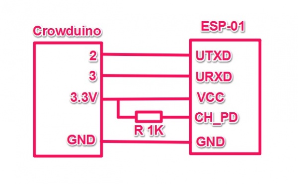
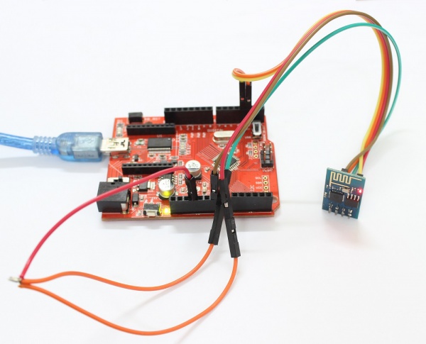
1.Hardware Connection.
Connected the Serial Wifi to U2 of the Crowtail- base shiled( D2 and D3) are used as software UART. Baud Rate:9600.
2.Connect the board to PC using USB cable.
3:Download the code: Webserver_for_ESP8266-01 or copy it to you new skecth.
#include <SoftwareSerial.h>

#define DEBUG true

SoftwareSerial esp8266(2,3); // make RX Arduino line is pin 2, make TX Arduino line is pin 3.
                             // This means that you need to connect the TX line from the esp to the Arduino's pin 2
                             // and the RX line from the esp to the Arduino's pin 3
void setup()
{
  Serial.begin(9600);
  esp8266.begin(9600); // your esp's baud rate might be different
  sendData("AT+RST\r\n",2000,DEBUG); // reset module
  sendData("AT+CWMODE=2\r\n",1000,DEBUG); // configure as access point
  sendData("AT+CIFSR\r\n",1000,DEBUG); // get ip address
  sendData("AT+CIPMUX=1\r\n",1000,DEBUG); // configure for multiple connections
  sendData("AT+CIPSERVER=1,80\r\n",1000,DEBUG); // turn on server on port 80
}

void loop()
{
  if(esp8266.available()) // check if the esp is sending a message
  {
    /*
    while(esp8266.available())
    {
      // The esp has data so display its output to the serial window
      char c = esp8266.read(); // read the next character.
      Serial.write(c);
    } */

    if(esp8266.find("+IPD,"))
    {
     delay(1000);

     int connectionId = esp8266.read()-48; // subtract 48 because the read() function returns
                                           // the ASCII decimal value and 0 (the first decimal number) starts at 48

     String webpage = "<h1>Hello World!</h1>";
     String cipSend = "AT+CIPSEND=";
     cipSend += connectionId;
     cipSend += ",";
     cipSend +=webpage.length();
     cipSend +="\r\n";

     sendData(cipSend,1000,DEBUG);
     sendData(webpage,1000,DEBUG);

     String closeCommand = "AT+CIPCLOSE=";
     closeCommand+=connectionId; // append connection id
     closeCommand+="\r\n";
     sendData(closeCommand,3000,DEBUG);
    }
  }
}


String sendData(String command, const int timeout, boolean debug)
{
    String response = "";

    esp8266.print(command); // send the read character to the esp8266

    long int time = millis();

    while( (time+timeout) > millis())
    {
      while(esp8266.available())
      {
        // The esp has data so display its output to the serial window
        char c = esp8266.read(); // read the next character.
        response+=c;
      }
    }

    if(debug)
    {
      Serial.print(response);
    }
    return response;
}
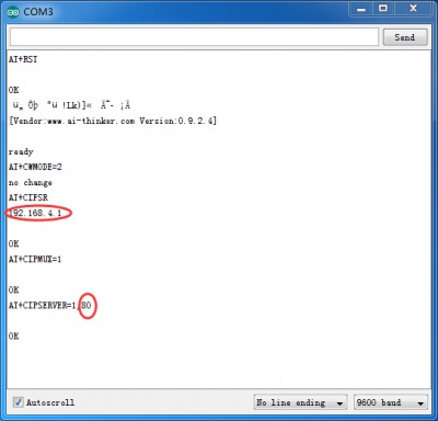
4.Upload the code and Open the serial monitor.You can see some configuration information.
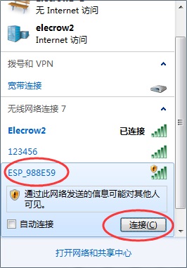
5.PC connect to the wifi of ESP8266.
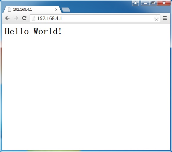
6.Then you can visit the Webserver of the ESP8266.
