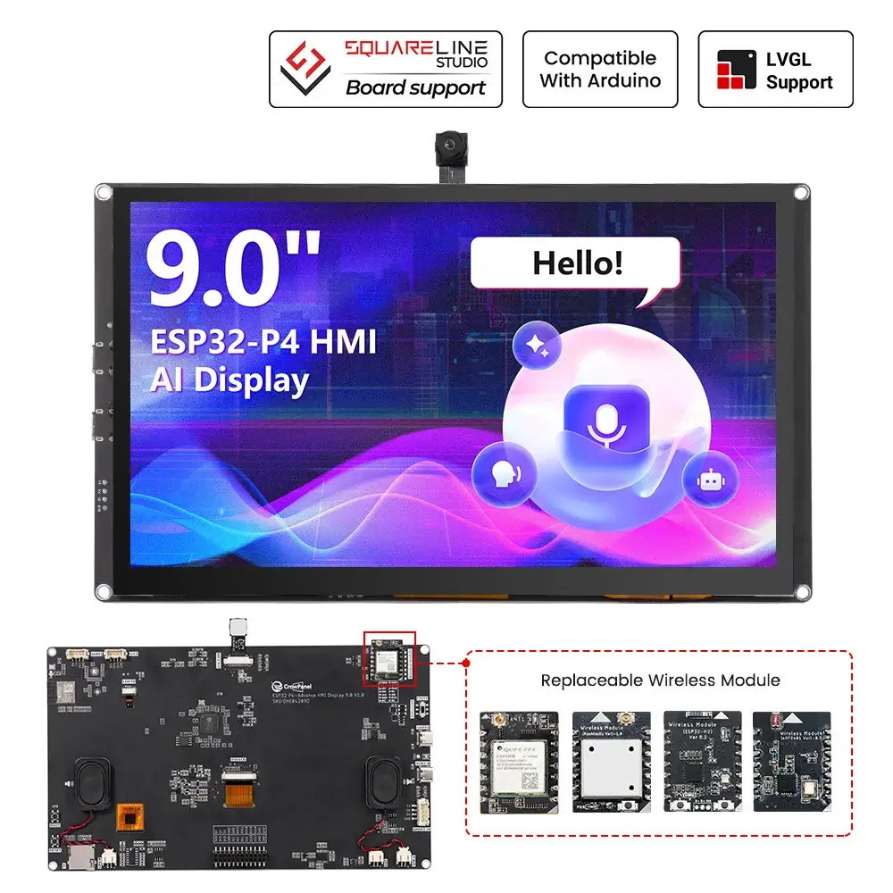
CrowPanel Advanced 9inch |ESP32-P4 HMI AI Display 1024x600 IPS Touch Screen with WiFi 6 Compatible with Arduino/LVGL
Model DHE04209D
Schematic:
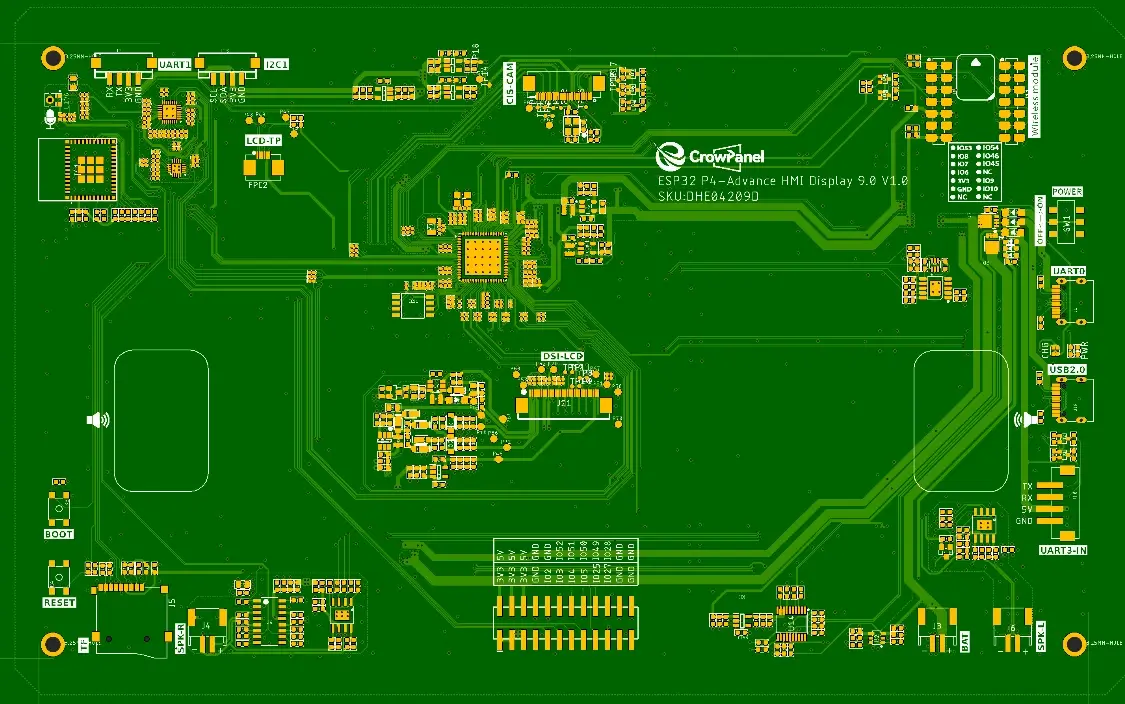
Functional description of the product's internal interfaces:
| Pin Name | Description | Connector Type |
|---|---|---|
| SPK | Output audio signals to connect to speakers. The main board comes with a power amplifier chip circuit. | PH2.0-2P |
| PWR | Power LED. | |
| CHG | Charging LED | |
| RST | Reset button. Press it to reset the system. | |
| boot | Used to enter programming mode or for button testing. Hold this button down while powering on, then release to enter download mode. Alternatively, after powering on, hold this button down, press the RESET button, release the RESET button, and then release this button to enter download mode. When download mode is not required, this button functions as a standard button. | |
| UART1 | Builds communication between Logic modules, including the serial communication module and the print module. | PH2.0-4P |
| I2C | Builds communication between Logic modules, including the serial communication module and the print module. | PH2.0-4P |
| UART3-IN | Input power supply and serial communication functionality | XH2.54-4P |
| BAT | Connect the lithium battery. (with battery charging circuit) | PH2.0-2P |
Product External Interface Functions:
| 5.0-inch HMI port | pin number | Electrical Characteristics |
|---|---|---|
| UART1 | RX(IO48); TX(IO47) ; | Output voltage: 3.3V Output current: 1A max. Use: Power supply output and communication. |
| UART3-IN | RX(IO33); TX(IO34) ; | Input voltage: 5V ± 5%. 5.5V max. Input current: 2A max. Purpose: Power supply input and communication. |
| I2C | SDA(IO45); SCL(IO46) ; | Output voltage: 3.3V Output current: 1A max. Use: Power supply output and communication. |
| SD Card | SD1_CMD(IO44); SD1_SCK(IO43); SD1_D0(IO39); CS(GND) | Maximum output current: 20mA Signal type: 3.3V logic level, digital control signal |
| LCD Backlight | LCD_BK_POWER(IO29); LCD_BK_EN(IO31)(PWM) | Maximum output current: 20mA Signal type: 3.3V logic level, digital control signal |
| PDM MIC | MIC_MCLK(IO24);MIC_SD2(IO26) | Maximum output current: 20mA Signal type: 3.3V logic level, digital control signal |
| SPK | Cavity Speaker YZ3020/3020 Square/4Ω 3W | |
| BAT | Input voltage: 3.7–4.2 V,Maximum intput current: 430mA |
ESP32-P4 9 inch and IPS Display Wiring Pins:
**DSI = Display Serial Interface**is a high-speed, low-power display interface standard defined by the MIPI Alliance, most commonly used in smartphones, tablets, Raspberry Pi devices, and embedded Linux systems.
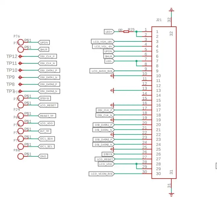
DSI Pin connection
DSI_DATAN0--IO40
DSI_DATAN0--IO39
DSI_DATAN0--IO36
DSI_DATAN0--IO35
DSI_CLKN--IO37
DSI_CLKP--IO38
DSI_REXT--IO34
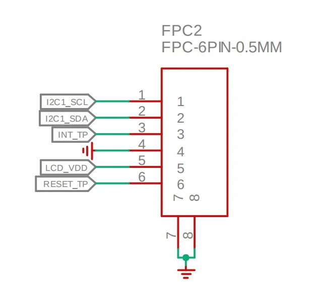
ESP32-P4 and Touch Driver Wiring:
i2c address: 0x5D/0x14.(The INT pin level during reset of the GT911 touch chip determines the device address.)
INT Low Level(0x5D);
INT High Level(0x14).
Pin connection
ESP32-P4 and wireless module wiring pins:
Output voltage: 3.3V Output current: 1A max. Use: The power supply communicates with the wireless module.
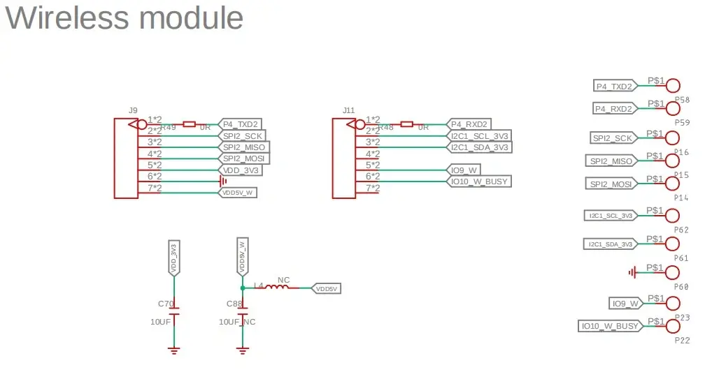
Pin connection
#define RADIO_GPIO_CLK 8
#define RADIO_GPIO_MISO 7
#define RADIO_GPIO_MOSI 6

#ifdef CONFIG_BSP_SX1262_ENABLED
#define SX1262_GPIO_BUSY 9
#define SX1262_GPIO_IRQ 53
#define SX1262_GPIO_NRST 54
#define SX1262_GPIO_NSS 10

#ifdef CONFIG_BSP_NRF2401_ENABLED
#define NRF24_GPIO_IRQ 9
#define NRF24_GPIO_CE 53
#define NRF24_GPIO_CS 54
ESP32-P4 and Audio out:
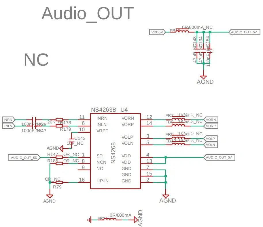
Pin connection
#define AUDIO_GPIO_LRCLK    21   // GPIO pin number for LRCLK (Left-Right Clock)
#define AUDIO_GPIO_BCLK     22   // GPIO pin number for BCLK (Bit Clock)
#define AUDIO_GPIO_SDATA    23   // GPIO pin number for SDATA (Serial Data)
#define AUDIO_GPIO_CTRL     30   // GPIO pin number for audio amplifier control
Program Download Tutorial Video(Click on the image):
[][video]
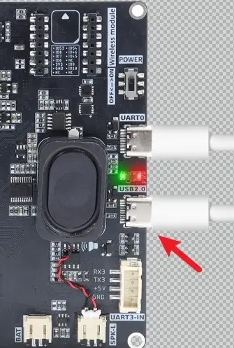
Introduction to UART 0 and USB 2.0:
Program downloads require the use of UART 0.

Note: Turn on the switch before use. Slide the POWER switch to the ON position.

If the program utilizes screen functions, power consumption will reach 8-10 watts. If powered solely by the computer's USB port, insufficient power may cause the screen to go black. It is necessary to connect a USB 2.0 port simultaneously for power supply.
If the UART0 connection does not display a serial port number, it may be due to missing serial port drivers. Download the CH341 serial port drivers and retest the connection.
Serial Port Driver for Mac:https://www.wch.cn/downloads/CH34XSER_MAC_ZIP.html
Regarding situations where serial ports remain inaccessible after installing drivers on a Mac, the following settings must be configured on the Mac:
- After installing the CH341 serial port driver, navigate to System Preferences.Click Login Items & Extensions.
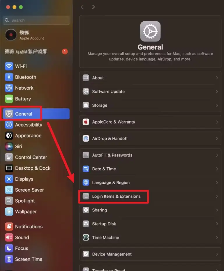
2.Click Driver Extensions.

3.Click Open, then click Done to save the settings.


USB 2.0:
USB 2.0 (Universal Serial Bus 2.0) is a common universal serial interface standard used to connect computers with various peripherals.
Its maximum transfer rate is 480 Mbps (High-Speed mode), representing a significant improvement over USB 1.1. This enables it to meet the data transfer needs of devices such as keyboards, mice, USB flash drives, printers, and webcams. USB 2.0 supports hot-plugging and plug-and-play for ease of use, while also providing 5V power supply (up to 500 mA) to peripherals.
Note: The shipped firmware does not include USB functionality. For those requiring USB features, please refer to our USB functionality course in Lesson 6.
NOTE:The firmware for the C6 module is pre-programmed at the factory and cannot be directly reprogrammed via P4.
Platforms Supported
Please click the card below and follow the instructions to install ESP_IDF.
The IDF version must be 5.4.2 or higher.
![]()
Version 1.1 Update
The C6 module version 1.1 adds support for 4-wire SDIO communication. Additionally, the arrangement of the SDIO pins has been adjusted, with the pin mappings of the data lines D0–D3 changing from IO14, IO15, IO16, IO17 to IO17, IO16, IO15, IO14.
Version 1.2 Update
Based on the V1.1 version, V1.2 further optimized the communication stability of the LoRa wireless module. At the same time, the signal pins of the wireless module socket were re-allocated: the original IO53 and IO54 were adjusted to IO27 and IO28 respectively, and correspondingly, IO27 and IO28 were adjusted to IO53 and IO54 respectively.
Courses on Different Platforms:
| AI Voice Chat Robot | SquareLine Studio | Arduino |
|---|---|---|
 |  | |
 |  | Arduino IDE View Tutorials -- V1.0 Arduino IDE View Tutorials -- V1.1 Arduino IDE View Tutorials -- V1.2 |

Resources
Github link:
(This GitHub link usually may contain 3D files, schematics, program code, factory firmware, factory sourcecode and other materials. Please click to view.)
How to buy
Please visit this page to purchase CrowPanel Advanced 9inch ESP32-P4 HMI AI Display.
Support
If you encounter any issues while using the service, you can contact us via the social media links in the bottom-right corner of elecrow or send an email to techsupport@elecrow.com for technical support.