**Apply Elecrow nRFLR1110 Wireless Transceiver Module -**Integrates Nordic nRF52840 and Semtech LR1110 with built-in LoRa chip and GNSS (GPS/Beidou) functionality
In this lesson, we will focus on how to use the GNSS (GPS/Beidou) function of the built-in chip in the nRFLR1110.
GNSS stands for Global Navigation Satellite System, which is a navigation and positioning system that uses artificial Earth satellites. It provides users with all-weather three-dimensional coordinates, speed, and time information at any location on the Earth's surface or in near-Earth space.
The basic working principle of GNSS is to determine the receiver’s position using triangulation based on the propagation time of satellite signals from satellites to the receiver and the satellite's position data. Specifically, the GNSS receiver simultaneously receives signals from multiple satellites, calculates the distance between itself and each satellite, and then determines the receiver's three-dimensional coordinates on Earth (longitude, latitude, altitude) based on these distances and the precise positions of the satellites.
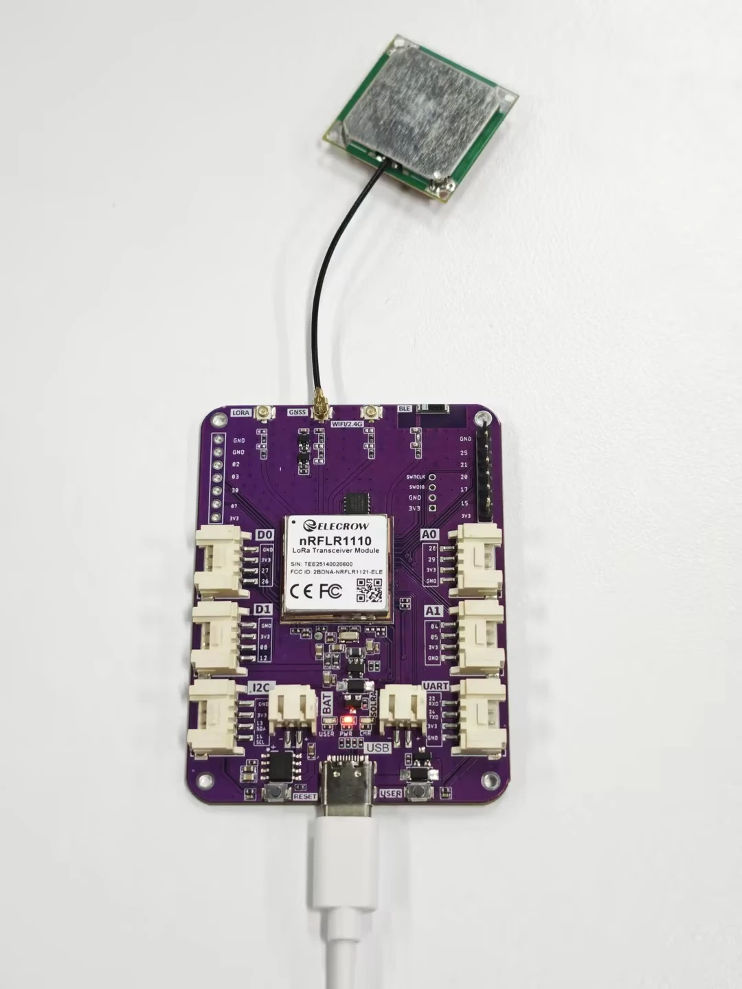
As shown in the figure below, the development board is connected to a dedicated antenna. Place the device in an open outdoor environment, and the nRFLR1110 will receive satellite signals and print the information via the serial port.
Next, let’s explore this topic together.
First, open the code file.
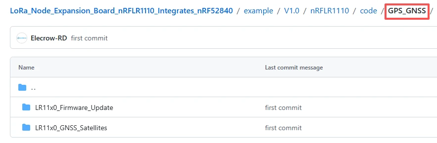
The GitHub download link for the code of this lesson is
Both code files are based on the RadioLib library, mainly used to operate the LR11x0 series wireless modules.
The LR11x0_Firmware_Update file is used to update the internal firmware of the LR11x0 module. (The module comes with firmware pre-installed)
The LR11x_GNSS_Satellites file is used to perform GNSS scanning and display the information of currently visible satellites.
Code 1: RadioLib LR11x0 Firmware Update Example
Select the firmware version to upload, in this case, version 4.01 of the LR1110. It is important to select the correct firmware to avoid potential hardware damage.This line of code is a macro definition instruction. Its function is to specify and enable the official firmware image with version number 0401 (i.e., version 4.1) for the LR1110 chip. It instructs the compiler to package the firmware data of this version into the program, which is used for subsequent firmware upgrade operations on the LR1110 chip.
Moreover, this version is a stable one that supports core functions such as GNSS/GPS positioning and WiFi scanning, and is a necessary prerequisite for running the second satellite scanning code.

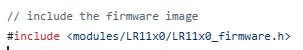
This line of code is a header file inclusion instruction. Its function is to, based on the selected LR1110 firmware version as defined by the above macro, introduce the corresponding complete firmware binary image data into the current program. This provides all the necessary firmware content for subsequent firmware upgrades to the LR1110 chip, and is an indispensable file inclusion operation for completing the firmware update of the chip.
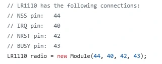
This line of code is used to create and initialize a radio instance object for controlling the LR1110 wireless chip. By passing in the four key hardware pin numbers of NSS, IRQ, NRST, and BUSY, a communication connection is established between the microcontroller and the LR1110 chip. All subsequent operations on the chip (such as initialization, firmware upgrade, reading version, etc.) will be executed through this radio object.
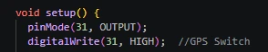
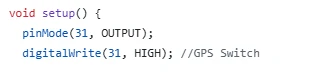
This section of code is located in the program initialization function"setup()", and is used to set the 31st pin of the microcontroller to output mode and output a high level, thereby activating the GPS power switch on the hardware to supply power to the GNSS positioning function of the LR1110 chip, ensuring that the subsequent firmware upgrade and satellite scanning functions can operate normally.
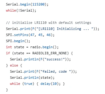
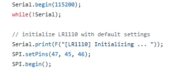
This code first initializes the serial communication at a baud rate of 115200 and waits for the successful establishment of the serial connection. Then, it configures and starts the SPI hardware communication bus. By calling the initialization method of the radio object, it configures the LR1110 chip with default settings and simultaneously checks the initialization status. If the initialization is successful, it prints a prompt message; if not, it outputs the error code and enters a deadlock shutdown, thereby completing the communication and hardware foundation initialization verification before the chip upgrade.
This line of code is used to call the custom version reading function in the program, to actively read the current device model, basic firmware, WiFi firmware and GNSS firmware version information from the internal part of the LR1110 chip, and to print and output these information completely through the serial port, which is convenient for confirming the current version status of the chip before firmware upgrade.

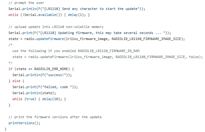
This code is the core execution stage of the entire firmware upgrade program. Firstly, it sends a prompt message to the user via the serial port, and waits for the user to send any character in the serial monitor before continuing the execution. This ensures a secure manual confirmation mechanism to prevent automatic incorrect upgrades. After confirmation, the program will write the complete firmware image data previously introduced through the communication bus into the non-volatile memory of the LR1110 chip. The upgrade process lasts for several seconds. Meanwhile, the program will monitor the upgrade status in real time. If the upgrade is successful, it will print a prompt message; if it fails, it will output the corresponding error code and enter a dead loop to stop running.
Finally, it calls the printVersions() function again to read and print the firmware version after the upgrade, to verify whether the version number has been updated successfully, completing the verification process of the entire firmware upgrade.
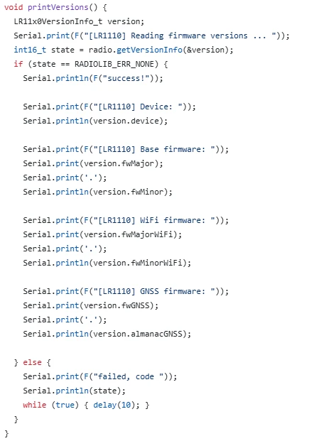
This code is a custom version information reading and printing function named printVersions(), specifically designed to obtain and display all the key version data of the LR1110 chip. Inside the function, a structure is first defined to store the version information. The getVersionInfo() method of the radio object is called to read the device model, basic firmware, WiFi firmware, GNSS firmware, and ephemeris version, among other core information from the chip. If the reading is successful, each item of the information is printed clearly in the serial port in a formatted manner, facilitating users to visually check the chip status. If the reading fails, an error code is output and the program enters a dead loop to stop.
This function is called once before and after firmware upgrade, and it is the core function for confirming the version changes before and after the upgrade and verifying whether the firmware update is effective.
Code 2: RadioLib LR11x0 GNSS Satellites Example
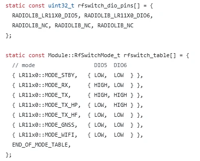
This code is specifically designed for the hardware RF Switch of the Wio WM1110 development board, and it is divided into two parts: pin definition and mode mapping table. The first part defines the pins DIO5 and DIO6 of the LR1110 chip as the ones used to control the RF Switch, while the remaining pins are marked as unconnected. The second part establishes a correspondence table between the working modes of the chip and the pin levels, clearly specifying the high and low levels that DIO5 and DIO6 should output in each mode such as standby, reception, transmission, GNSS positioning, WiFi scanning, etc.
This enables the chip to automatically control the external RF Switch to switch to the corresponding antenna channel when switching between different functional modes, ensuring that GNSS, wireless communication, and other functions can normally transmit and receive signals. It is a key hardware configuration that ensures the normal operation of the module's satellite search and communication functions.
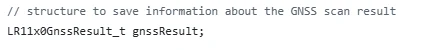
This line of code is designed to define a structure variable named "gnssResult", which serves as a container specifically for storing all the core result data returned by the LR1110 chip after performing GNSS satellite scanning. This variable will store crucial information such as whether the scan was successful, the total number of satellites detected, and satellite data cache. Subsequent programs can obtain the complete result of this GNSS scan by reading this variable, and it is the basic data carrier for reading, parsing, and printing satellite information.
This code is the core initialization function of the GNSS satellite scanning program, named "setup()". It is executed only once after the program is powered on and is responsible for completing all the preparatory work for startup: Firstly, pin 31 is set as an output and raised to a high level, the hardware power switch of the GPS module is turned on to ensure that the GNSS function is powered;
then, the serial communication is initialized at a baud rate of 115200 and waits for the successful connection with the computer to facilitate real-time output of debugging and scanning information; next, the SPI communication pins are configured and the SPI bus is started to establish a high-speed communication channel between the microcontroller and the LR1110 chip;
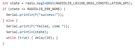
the most crucial part is to call the "beginGNSS()" function to specifically initialize the GNSS positioning function of the chip and specify the use of the GPS satellite constellation. Throughout the process, the initialization status is monitored, and if successful, a prompt message is printed; if failed, an error code is output and the program enters a dead loop to stop.
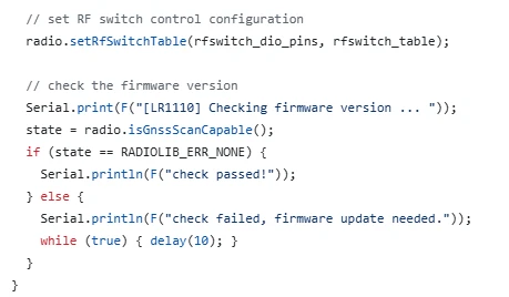
This code is located in the initialization stage of the GNSS scanning program. Firstly, the previously defined RF switch pins and the mode configuration table are loaded into the LR1110 chip, enabling the chip to automatically switch the antenna working mode and ensuring the normal reception of GNSS signals. Subsequently, the isGnssScanCapable() function is called to check whether the current chip firmware version supports the GNSS scanning function. If the check passes, a verification success message is printed and the program continues to run. If the firmware version is too low to support the GNSS function, a failure prompt is printed and the program is forced to enter a dead loop to stop execution.
This ensures that only when the hardware configuration is correct and the firmware version meets the requirements can the subsequent satellite scanning operations be performed, avoiding functional abnormalities caused by firmware or configuration issues.
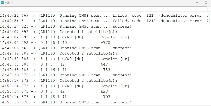
This code is the main loop function loop() of the GNSS satellite scanning program. The program will execute infinitely, and its core function is to continuously drive the LR1110 chip to perform GNSS satellite scanning operations: Firstly, it calls the gnssScan() function to start the satellite search and stores the scanning results in the gnssResult variable.
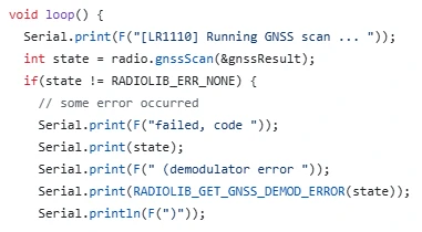
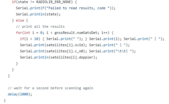
If the scan fails, it outputs detailed error codes and demodulation error information through the serial port;if the scan is successful, it first prints the total number of detected satellites, then reads the detailed data of all satellites in batches using the getGnssSatellites() function, including satellite numbers, signal carrier-to-noise ratio (C/N0), and Doppler frequency shift.
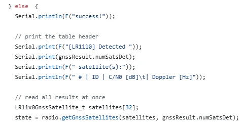
Subsequently, it formats and outputs these data clearly to the serial port to facilitate users to visually check the satellite status and signal quality. After completing one scan, there is a 1-second delay, and then the next round of scanning is automatically initiated to achieve a continuous and cyclic GPS satellite monitoring function.
Now that the code explanation is complete, let's pay attention to the following points.
Notes:
1.Install the development version
Lastly, here are some points to keep in mind during actual operation:Since the nRFLR1110uses the nRF52840 as the main control chip, you need to install the nRF52 development board.
Open the Arduino IDE.
Go to File > Preferences (or Arduino > Preferences, depending on your operating system).
In the "Additional Board Manager URLs" field, add the following URL:
https://adafruit.github.io/arduino-board-index/package_adafruit_index.json
If there are already other URLs, make sure to separate them with commas or new lines.
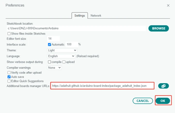
Click "OK" to save the settings.
Navigate to Tools > Board > Boards Manager.
In the search box, type "Adafruit nRF52", find "Adafruit nRF52 by Adafruit", and click "Install".(Here we are using version 1.7.0.)
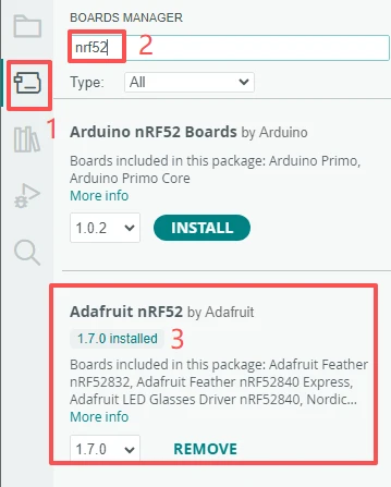
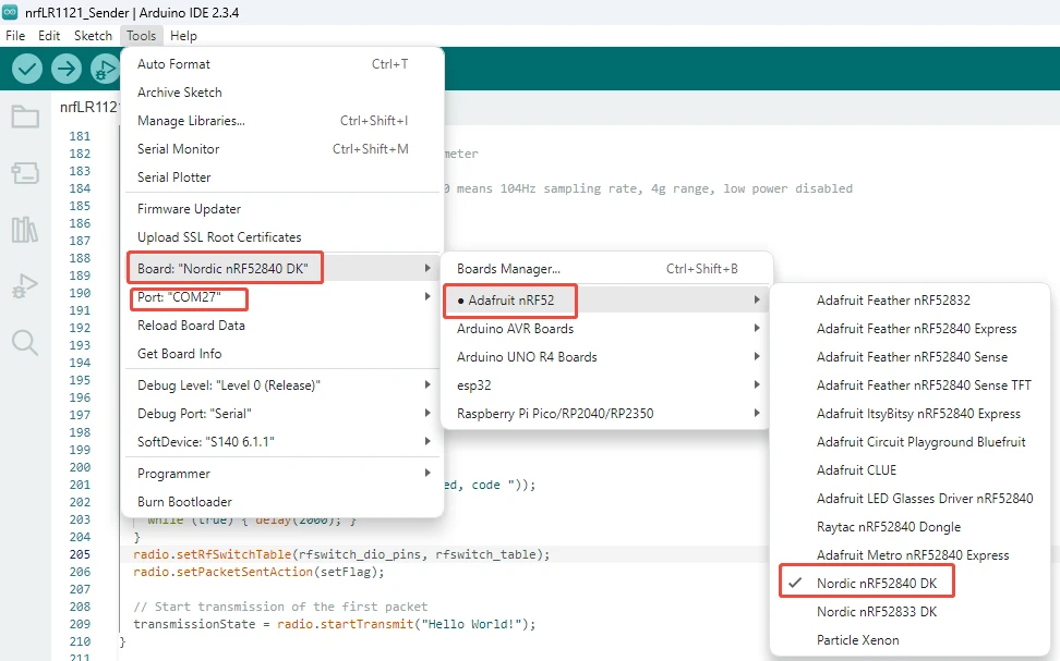
Once installation is complete, you can select the appropriate board model from the Tools > Board menu.
2.Use the library files we provided
Click on the link to our library file for download:
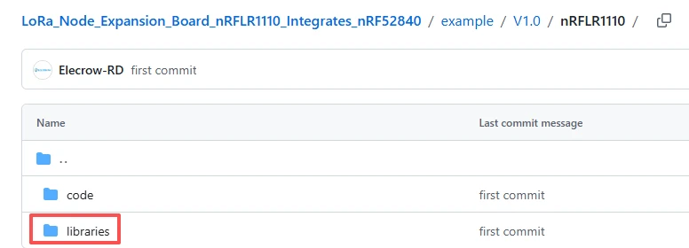
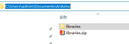
After the download is complete, place these four library files in this directory on your computer.
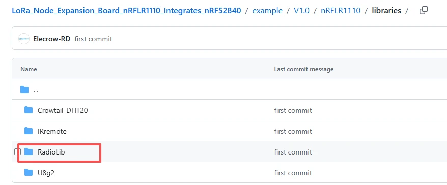
Place these four library files in the following path on your computer, in the "libraries" folder.
3.Pay attention to the configuration during the flashing process.
Result:
By examining the information transmitted via the serial port, one can obtain an understanding of the satellite information received at that time.
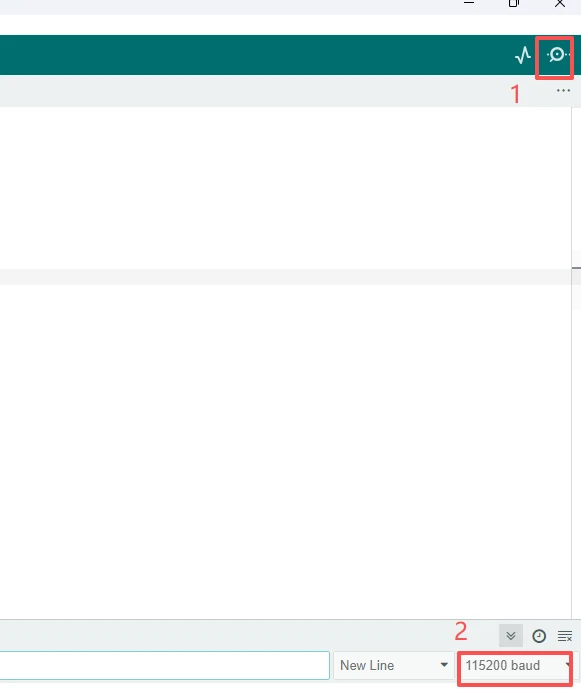
Open the serial monitor that comes with Arduino IDE and set the baud rate to the value specified in the code, which is 115200.
At this point, the above information from the loop function is printed in the serial monitor.