Lesson10 Create a 3D Printer UI Project on ESP32 Display
Project Introduction:
The 3D printer interface is a UI project based on Squareline studio software, which uses other components such as rollers and switches, as well as text boxes and buttons, to allow users to easily adjust the printer's parameters.
Introduction to Knowledge Points:
The following is a basic introduction to the components used in the project:
Roller: A roller is a control used to adjust values or parameters, typically consisting of a rotating disc and a central indicator. Users can adjust values or parameters by rotating the disc, and the indicator will move to display the current value or parameter. Roller components are typically used in 3D modeling, graphics design, game development, and audio editing.
Switch: A switch is a control used to switch states or options, typically consisting of a toggle button and a text label. Users can switch states or options by clicking the button, and the text label will update to display the current state or option. Switch components are typically used in setting panels, configuration options, and user settings.
In Squareline Studio, designers can customize the appearance and functionality of roller and switch components, such as adjusting their size, color, shape, and label. In addition, these components have responsive design, adapting to different screen sizes and resolutions to provide a better user experience. The UI content will be showcased using an ESP32 Terminal 3.5 inch RGB screen as an example.
Project Steps:
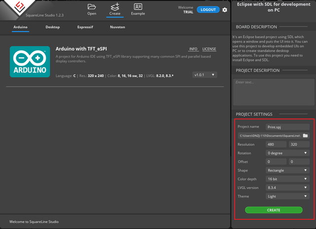
1 Create a new project in Squareline Studio as before. First, select the Arduino module, and then make some simple settings for the project, such as the project name and display size. Click Create to continue.
2 Add two buttons and two labels to display the content of the buttons. Adjust their positions as shown in the figure and set the appropriate display properties.
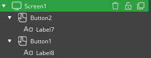
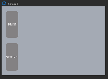
3 Add a slider component to simulate the printing progress. Add a label below the slider to display the progress value.
① Add the slider and label components, with the label located under the progress bar. Use the mouse to adjust their positions.

②Add related assets. At the bottom of the software, there is an Assets component. Click Add Assets and select the required assets to add them.
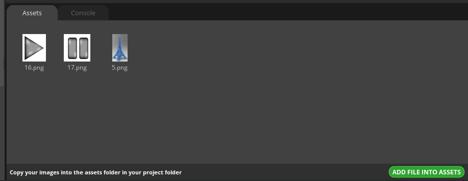
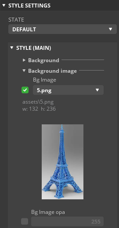
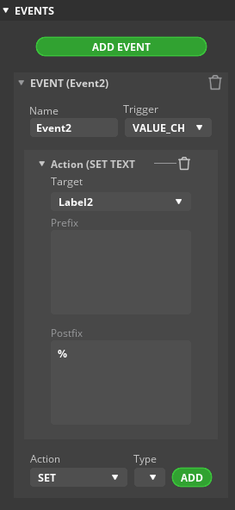
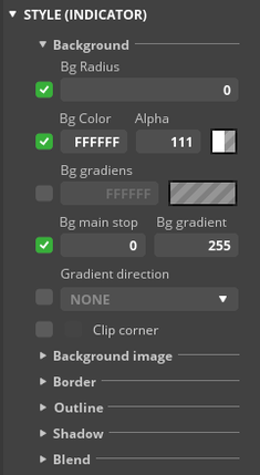
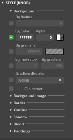
③Set the progress bar. Set the background image, event, indicator, and KNOB display properties of the progress bar.
- Set the background image
- Set the event
- Set the indicator
- Set the KNOB
- Full effect
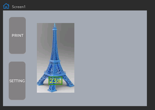
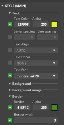
④Set label display properties;
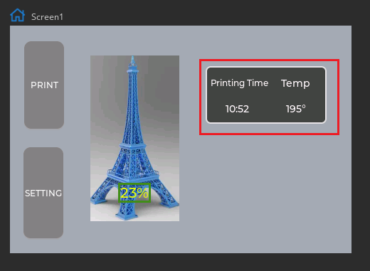
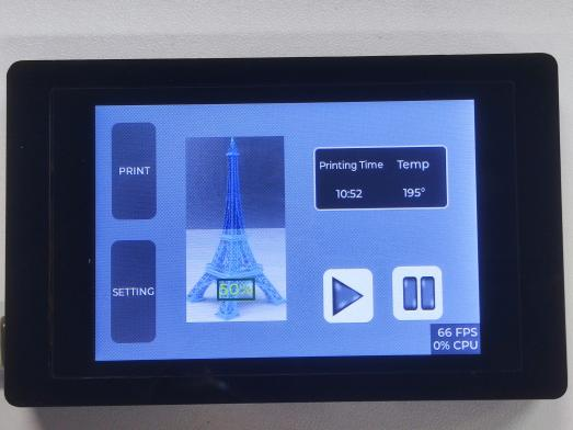
4 Add a panel to display the printing status. Add four labels below the panel to display the printing time and temperature.
①Add the panel and four labels below it.
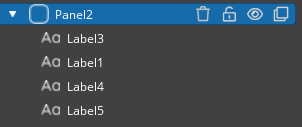
②Set the panel properties and label contents as shown in the figure.
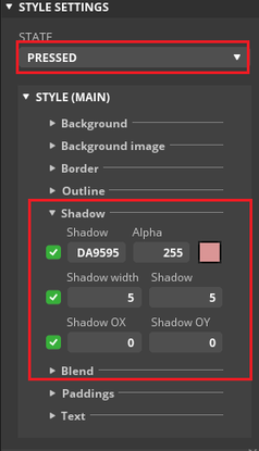
5 Finally, add two buttons, add button images, and set the shadow effect when the button is pressed.
① Add the buttons and button images.
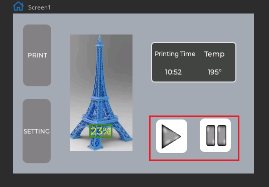
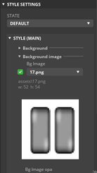
② Set the shadow state when the button is pressed. Make the same settings for both buttons.
6 Click Screen 1 and then click Copy Page to generate the same page.
① Delete the extra components and leave only the button components to switch pages.
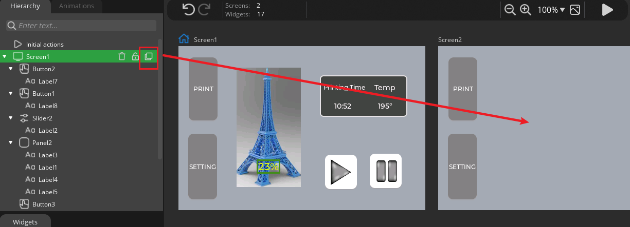
② Set the Screen 2 button to switch pages. Make the same settings as for Screen 1.
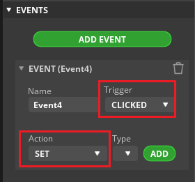
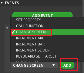
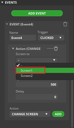
③ Select the target page to switch to. Select Screen 1 for the PRINT button and Screen 2 for the SETTING button. Make the same settings for both buttons on both screens.
①Drag two panels and add a Roller component under each panel. Use the mouse to move the components and adjust them to the appropriate position.

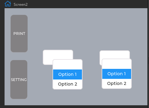
②Use the mouse and position parameters to adjust the position of the components. Enter the Roller component to set the data parameters.
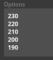

③Adjust the background color and other related properties according to the background requirements.
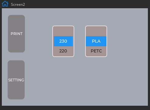
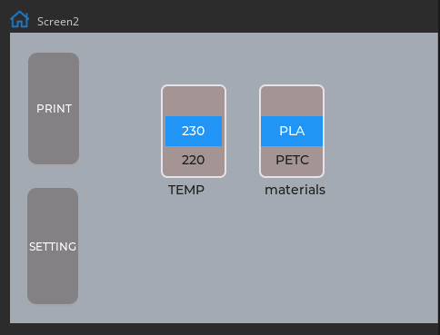
8 Add two labels below the selection to indicate the temperature and material.
9 Finally, set the fan switch to control the fan.
①Drag two Switch components and adjust their positions by moving the components with the mouse.
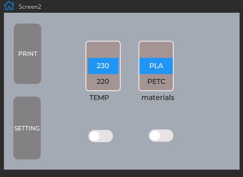
②Drag two label components and place them below the switch to identify FAN 1 and FAN 2.
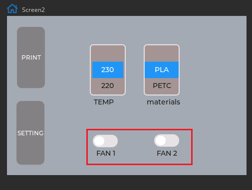
③Set different page targets for the two buttons.
After all settings are completed, click Run to see the effect.
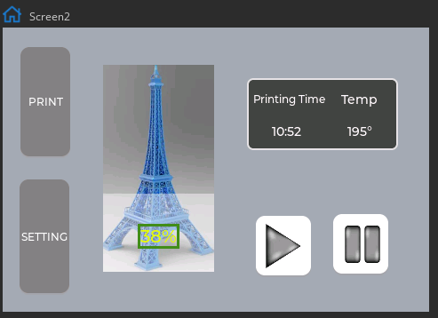
Running effect:
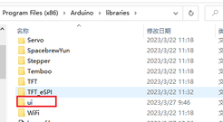
①Click Export in the software to generate the UI file and place the new UI file in the Arduino library. Then download the LVGL_RGB example provided by the official to the ESP32_rgb terminal.
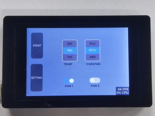
②After the program is successfully downloaded, check the effect on the screen.
Summary:
This project helps beginners to quickly understand the basic usage of the Roller and Switch components and adds page jump function to replicate the UI interface of a 3D printer, which is very practical. In practical applications, it can be modified and extended according to needs, adding more settings and functions.
HMI Display Tutorial Contents
- Lesson01 Introducing the ESP32 Display series and environment configuration
- Lesson02 Start the ESP32 DISPLAY GUI drawing via LovyanGFX Graphics Library
- Lesson03 How to Display Pictures on ESP32 Boards
- Lesson04 LVGL Basics: How to install LVGL for ESP32 Displays
- Lesson05 Introduction to the 5 categories of LVGL GUI library Widgets
- Lesson06 Use Squareline Studio to start your 1st human machine interface project
- Lesson07 How to implement text information input with Squareline Studio
- Lesson08 How to make the menu and a progress bar with Squareline Studio
- Lesson09 How to make an analysis report on ESP32 Display
- Lesson10 Create a 3D Printer UI Project on ESP32 Display
- Lesson11 How to Make a Mixer Interface on ESP32 Display
- Lesson12 Make Your ESP32 Display the Lantern Control terminal
- Lesson13 DIY Electronic Control Terminal on ESP32 Display with Squareline Studio
- Lesson14 Create Car Control Screen on ESP32 Display: A Step-by-Step Guide
- Lesson15 Smart Agriculture Monitoring: IoT-Based Real-Time ESP32 Display Project
- Lesson16 ESP32 Display for Smart Home Central Control: A Home Automation Solution
