LRCC68 Point-to-Point Communication
In this lesson, we will focus on how to use the LRCC68 to transmit data.
LRCC68 is a low-cost, ultra-low-power, and ultra-compact pure RF LoRa® module based on the high-performance Semtech LLCC68 LoRa® wireless communication IC. It supports LoRa and LoRaWAN frequencies ranging from 868 to 915 MHz and mainly uses the new generation of LoRa™ modulation technology for ultra-long-distance spread spectrum communication.
The LRCC68 module is equipped with a high-quality TCXO oscillator, ensuring stable operation under industrial high and low temperature environments. It is specifically designed for wireless sensor networks and other IoT devices, especially those that require battery power, low power consumption, and long-distance connectivity. The module interfaces externally via SPI, and users can achieve wireless data transmission and reception through IO connections with an MCU. (Note: Since this module is a pure RF transceiver, it must be driven by an MCU or a specialized SPI debugging tool.)
LRCC68 is a LoRa wireless communication module based on the Semtech LLCC68 chip, designed for the 868MHz and 915MHz frequency bands. It uses an ultra-compact, surface-mount stamp hole design for easy integration into mainboards. The module adopts advanced LoRa modulation technology, which provides stronger anti-interference capability and longer communication range compared to traditional FSK and GFSK.
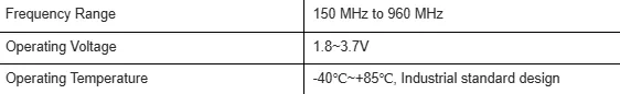
Its maximum transmission power can reach +22dBm, supporting a transmission rate of 1.76 to 62.5 kbps, and covers the global LoRa & LoRaWAN ISM frequency range of 850 to 930 MHz. Equipped with a high-quality TCXO crystal oscillator, it is resistant to extreme temperatures and runs stably with a sleep current as low as 1.62μA, making it especially suitable for smart home applications, wireless meter reading, scientific research, medical use, and medium-to-long distance wireless communication devices.
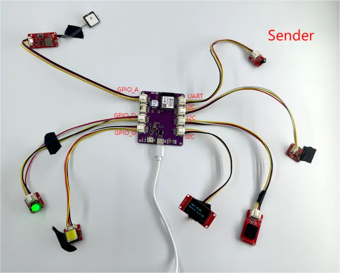
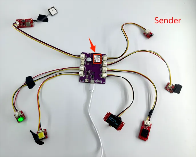
As shown in the figure below, we are using the LRCC68 module with each interface connected to a sensor. This setup allows us to collect data from each sensor and transmit the data to another LRCC68 module using LoRa technology. Finally, the received data can be viewed through the serial port.
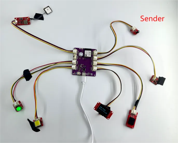
Next, let’s explore this together.
First, open the code files.
The LRCC68_Sender file is used to collect sensor data and transmit it.
The LRCC68_Receiver file is used to receive the data.
Code Link:
Let's first introduce the code structure of the sender.
We'll go through it module by module:
Bulb: Connected to the LRCC68 module's GPIO_D interface, which corresponds to pin 12
Button: Connected to the LRCC68 module's GPIO_D interface, which corresponds to pin 14
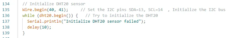
DHT20 Temperature and Humidity Sensor: Connected to the LRCC68 module's I2C interface, which corresponds to pins 40 and 41
Accelerometer: Also connected to the LRCC68 module's I2C interface, pins 40 and 41
u8g2 Display: Connected to the LRCC68 module's I2C interface, pins 38 and 39
IR Receiver: Connected to the LRCC68 module's UART interface, which corresponds to pins 19 and 20
GPS Module: Connected to the LRCC68 module's GPIO_A interface, which corresponds to pins 15 and 16
Next, let’s first talk about the implementation of the bulb and the button.
Light bulbs and buttons
The main function is to turn the bulb on or off by pressing the button.
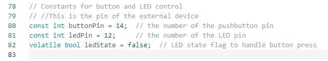
First, define the pins for the two interfaces.
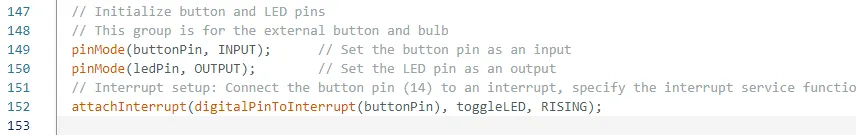
Then, in the setup function, configure the pins as input or output and set the interrupt condition. Interrupt configuration: connect the button pin (14) to an interrupt, assign the interrupt service routine to toggle the LED, and set the trigger condition to rising edge (i.e., when the button is pressed).
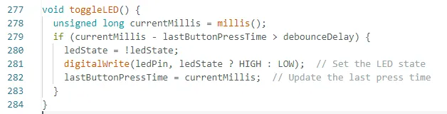
And then, set the logic for turning the bulb on and off.
DHT20 Temperature and Humidity Sensor
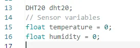
Initialize the libraries and variables to be used first.
Then initialize the temperature and humidity sensor in setup.
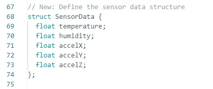
The structure defined here contains the values for temperature, humidity, and acceleration in three directions.
The purpose is to later transmit all this data together to another LRCC68 module.
Next, in the loop function, retrieve the temperature and humidity values and store them in the temperature and humidity variables within the structure.
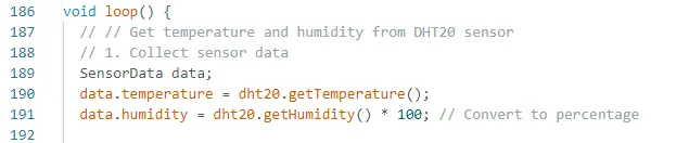
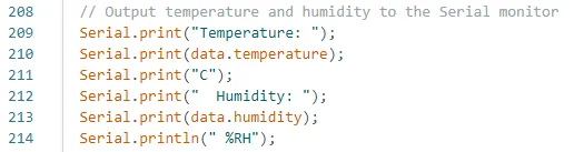
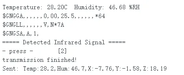
After retrieving the temperature and humidity values, you can print them to the serial monitor to check the values.
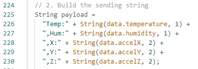
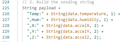
Then, combine them into the payload variable for easier transmission together.
Here, LoRa technology is used to transmit the data.
Accelerometer
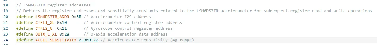
First, according to the technical manual of the LSM6DS3 accelerometer, explain and define its relevant registers.
Since both the accelerometer and the temperature and humidity sensor use the I2C protocol, their pins have already been initialized.

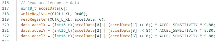
Then, in the loop function, repeatedly retrieve the acceleration values in all three directions.
The writeRegister and readRegister functions are custom functions we’ve written.
(You can refer to the code for more details, as the comments provided are quite detailed.)
writeRegister: Writes data to a register
readRegister: Reads data from a register
After obtaining the acceleration data, combine it into the payload variable for easier transmission together.
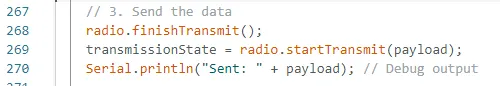
Finally, transmit the data to another LRCC68 module.
U8g2 display screen
In this experiment, we also added a display to show the temperature and humidity values.
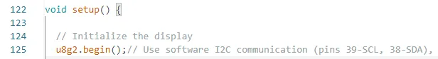
At the beginning of the code, the display configuration is initialized.
Although the display also uses the I2C interface, here we are using software-based I2C.

And in the setup function, initialize the display.
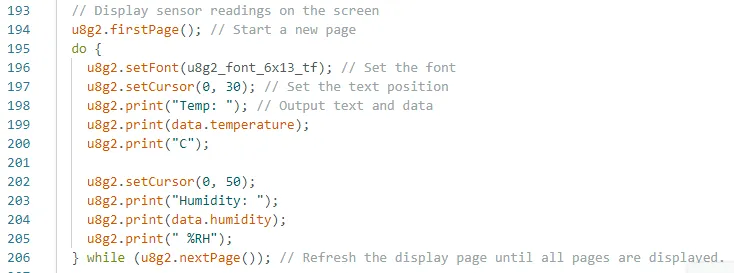
Then, in the loop function, set up the display and continuously update the displayed values.
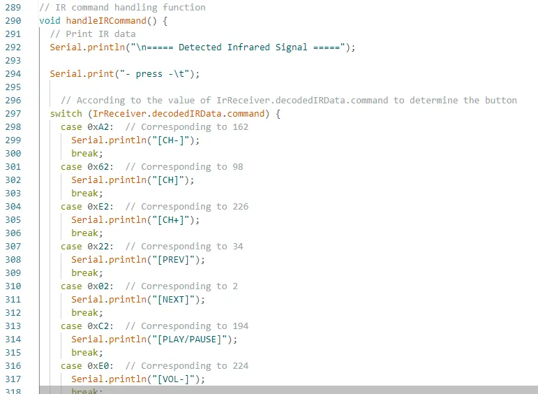
IR Receiver
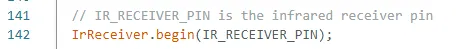
Initialize the pin 19, which is connected to the infrared sensor.

Then, initialize the infrared receiver sensor in the setup function.
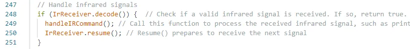
In the loop function, continuously process and receive the infrared signals sent by the remote control.
You can specifically map the key values represented by the infrared remote control buttons.
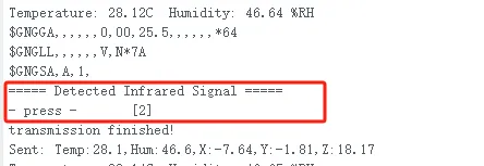
Here, I pressed the key value "2" on the infrared remote control.
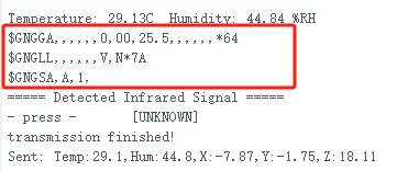
After receiving the infrared signal, the corresponding information will be displayed in the serial monitor as shown below.
GPS positioning module
Since the GPS module is connected to the GPIO_A interface, we initialize the UART interface pins 15 and 16.
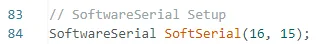
Then, initialize the baud rate required for the serial communication.

In this while loop, as long as there is available data on the software serial, the loop body will continuously execute. The SoftSerial.read() function reads a byte of data from the software serial and stores it in the incomingByte variable. Then, the received byte is printed to the hardware serial (usually connected to a computer for debugging and data monitoring) using Serial.print(incomingByte). Next, the received byte is stored in the buffer array, and the count variable is incremented to track the number of bytes stored. When count reaches 256, the loop exits to prevent an array overflow.
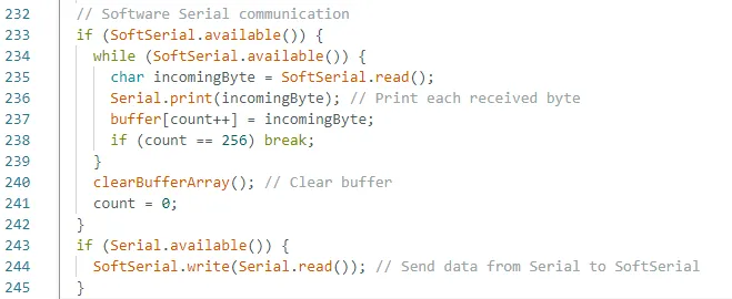
As you can see here, we haven't processed the received GPS signals. If you're interested, you can explore it further to obtain the desired latitude and longitude information.
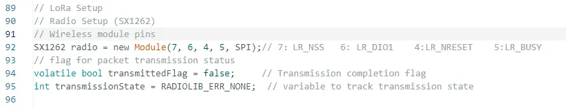
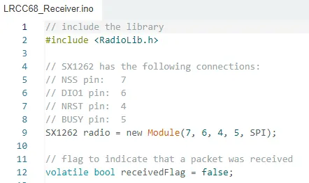
LoRa module
First, initialize the pins for the LoRa module.
You can open the schematic diagram we provided.
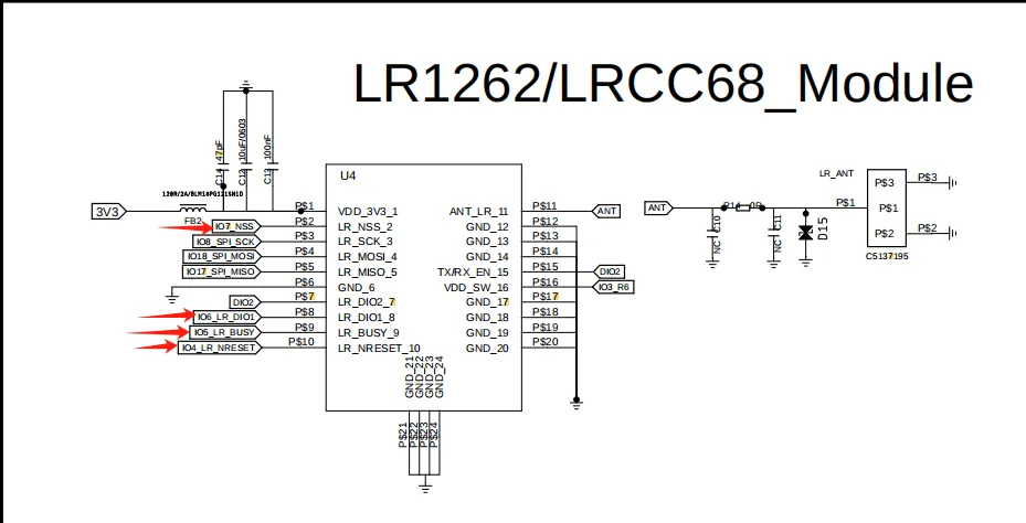
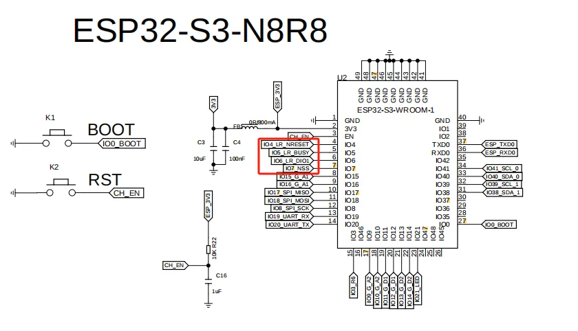
In our schematic diagram, you can identify the pins required for the LoRa module based on the ESP32-S3 chip's pins.
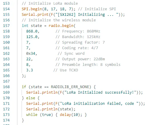
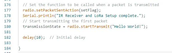
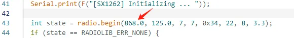
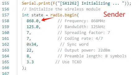
In the setup function, configure the relevant settings for the LoRa module.
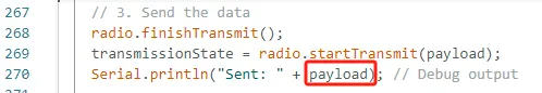
Finally, in the loop function, repeatedly send the data collected from the sensors.
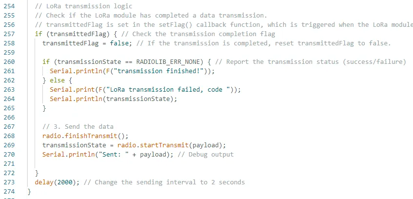
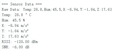
The overall data sent by the transmitter is shown in the diagram below.
This is the overall structure of the transmitter. Next, let's take a look at the code structure for the receiver.
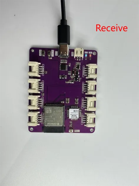
Receiving end
The receiver also starts by initializing the pins for the LoRa module.
Next, the most important thing is that the frequency band must match the one used by the transmitter.
Next, the data sent by the transmitter needs to be parsed.
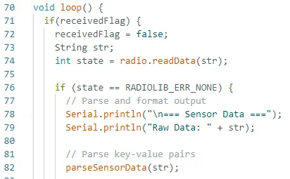
The parseSensorData function is a parsing function I wrote. I won't go into detail here, but its purpose is to parse the data that was packaged and sent over.
You can compare the sent message with the received information.
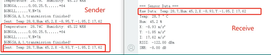
Perfect! The LoRa module successfully transmitted the data!
This concludes the explanation of the transmitter and receiver code.
Lastly, here are some points to keep in mind during actual operation:
-
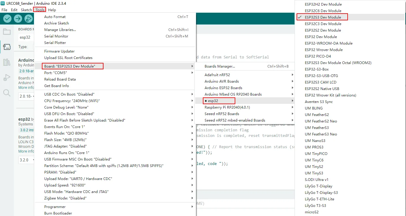
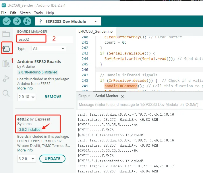
Since the LRCC68 uses the ESP32-S3 as the main control chip, you need to install the ESP32 development board.
-
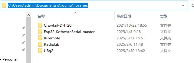
Use the library files we provided
(Reference path).
-
Pay attention to the configuration during the flashing process.