Example: The LR1262 Node Board uploads data to TTN server via Thinknode G1
Communicate with the gateway through the created TTN application node and upload the node-gateway communication data to the TTN server
Prerequisites:
1. The gateway has been created in TTN, and the Thinknode G1 gateway has been connected and operated normally.
2. Node applications (OTAA/ABP) corresponding to the band range of the gateway have been created in TTN
hardware preparation:
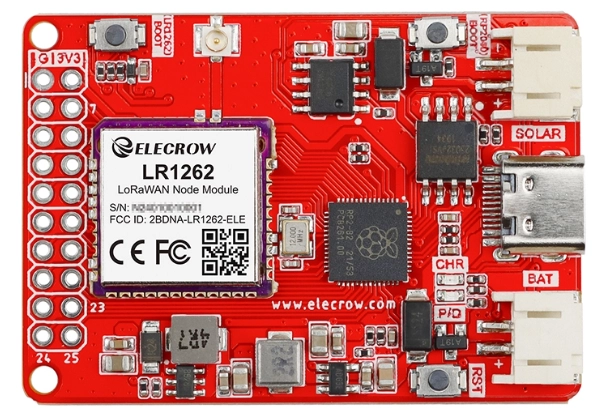
1.LR1262 Node Board
2.PC
3.TYPE-C cable
4.Thinknode G1
Getting Started Quickly with the Gateway
Gateway Network Configuration
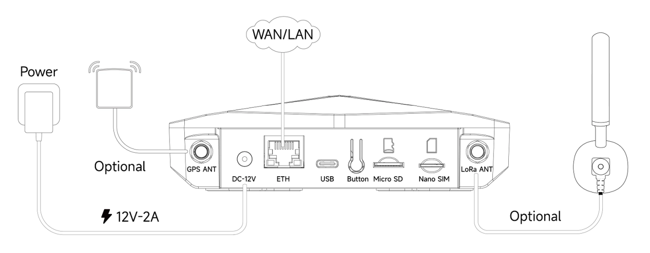
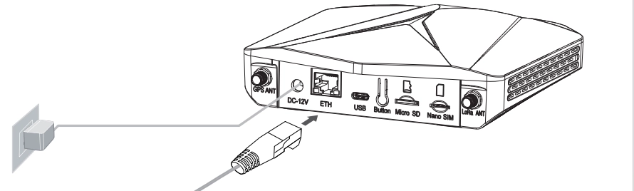
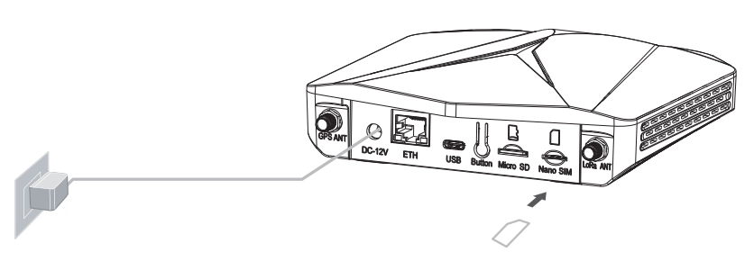
Connect the Lora antenna and power adapter to the gateway. The power indicator will show green and after about 15 seconds the top indicator will flash green to indicate that the gateway is booting up.
Configuring Gateway Networking Methods: There are 3 networking methods, Ethernet, Wifi, and 4G Cellular (for 4G version only)
Logging into the Local Console via Device AP Hotspot Access:
All 3 networking method settings should be done by logging into the local console first, and then proceeding to the configuration of the networking method
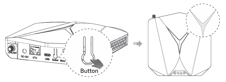
Step 1: Turn on the Device AP Hotspot
By long press the Button Setup button for 5S until the top indicator light turns blue and flashes slowly to enter the configuration mode
Step 2: Connect to the AP hotspot. The AP hotspot name is ThinkNode-G1_XXXXXX (6-digit MAC address), no password is needed, you can connect directly; connect your computer/cell phone to this AP hotspot.

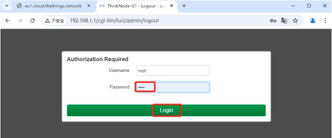
Step 3: Login to Local Console
Enter the IP address (192.168.1.1) in the browser to access the local console, then login account:root,enter password:root,and click the login button
Ethernet Connection
Step 1: Configure the Gateway Networking Mode as Ethernet Connection
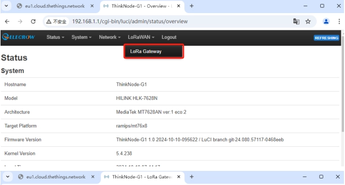
Click LoRaWAN in the Luci interface and navigate to the LoRa Gateway interface.
Select “ETH” as the networking mode.
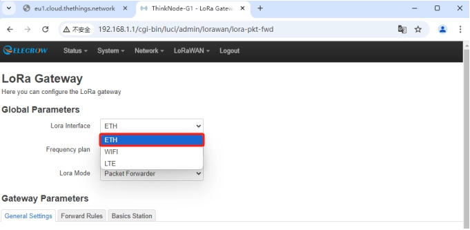
Then click - Save and Apply to apply your settings.
Connect the network cable to the network port, if the gateway is successfully connected to the Internet, the WLAN green light will be always on, and the top light will be always green.
WIFI Connection
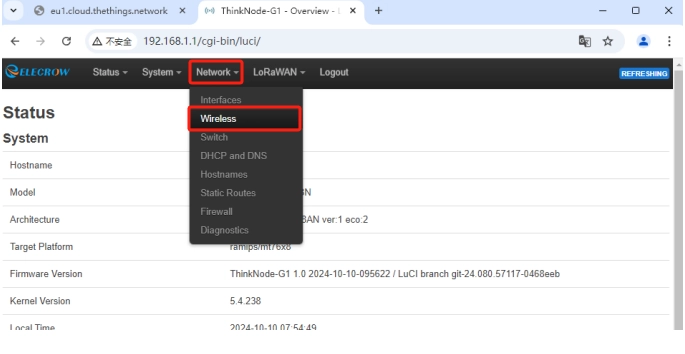
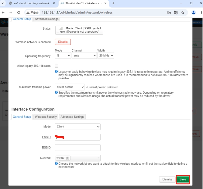
Step 1: Login to Luci page, click Network-Wireless
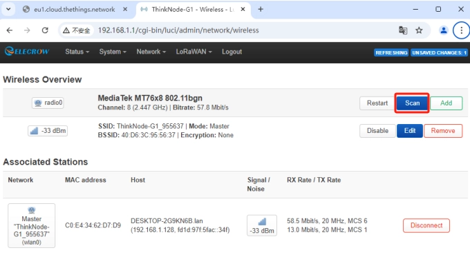
Step 2: Click the button Scan WIFI "scan"
Step 3: Select your WI-FI to join the network.
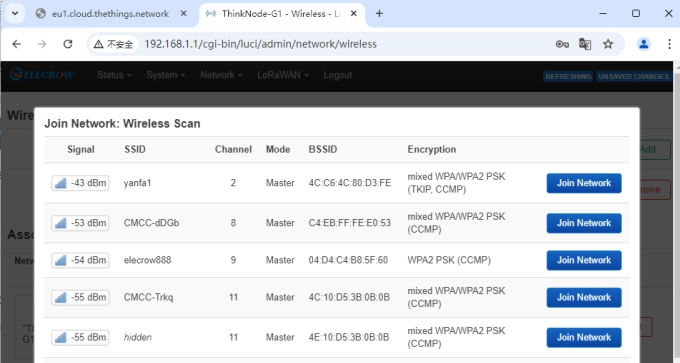
Step 4: Submit the Wi-Fi password and click Submit, and Save.

Step 5: Set the gateway networking mode to Wifi connection
Click LoRaWAN in Luci interface, navigate to LoRa Gateway interface.

Select “WIFI” as the network mode.
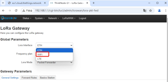
Then click -Save and Apply to apply your settings.

If the gateway successfully connects to WIFI, the WLAN green light will be always on and the top light will be always green.
Cellular Connection (for 4G version)
Step 1: Insert the SIM card into the Nano-SIM card slot
Step 2: Set the gateway networking mode to 4G cellular connection
Click LoRaWAN in the Luci interface and navigate to the LoRa Gateway interface.

Select “LTE” as the Networking Mode.

Then click - Save and Apply to apply your settings.
If the gateway is successfully connected to the 4G network, the LTE green light will blink and the top light will be green.
Checking the connection status of the gateway
After the gateway is powered on, you can check the working status of the gateway by the LED indicator:
Top LED status indicator
| Mode | Description | |
|---|---|---|
| Green | Solid | Operating normally, good internet connection. |
| Slowblinking | Device/ThinkNode is starting up. | |
| Blue | Slowblinking | Configuration mode, will automatically exit if there is no activity in 5 minutes. |
| RapidBlink | Device reset indication, press the button for 20 seconds, the light will flash rapidly. | |
| White | Solid | Download OTA upgrade firmware |
| Slowblinking | Upgrade burned OTA firmware | |
| Red | Solid | Hardware issue or internet connection failure. |
Individual LED indicators
| Mode | Description | |
|---|---|---|
| PWR | ON | Device powered on. |
| OFF | Not connected to power. | |
| LoRa | ON | Connected to LoRa wireless network. |
| OFF | Not connected | |
| WLAN | ON | Connected to WLAN Ethernet network. |
| OFF | Not connected. | |
| LTE | ON | The 4G module is powered on properly, but is not connected to the 4G cellular network |
| Blinking | Connected to 4G cellular network. | |
| OFF | Not connected. |
Button Function Description
| Mode | Description |
|---|---|
| Double Click | Software quick reboot. |
| Press for 5s | Slow blue light blink, entering configuration mode, will automatically exit if there is no activity in 5 minutes. |
| Press for 20s | Rapid blue light flash, triggering factory reset and software reboot. |
Connecting to the TTN
There are two ways to connect to the Things Network: the Packet forward and the Basics™ Station. choose one of the ways to connect to the gateway. the ThinkNode gateway is configured with Packet forward by default.
The Semtech UDP packet forward is the original LoRaWAN® packet forward, which connects to the server via the Semtech UDP protocol.
The LoRa Basics™ Station is the preferred way to connect the gateway to The Things Stack.
Connecting via Packet Forwarder The Semtech UDP Packet Forwarder is the original LoRaWAN® packet forwarder that connects to the server via the Semtech UDP protocol.
TTN Configuration
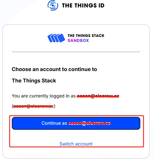
Step 1: Log in to The Things Stack (console.cloud.thethings.network). If you do not have a TTN account, register first.
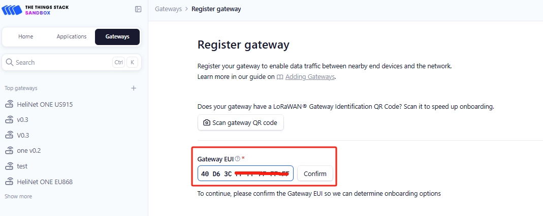
Step 2: Register the Gateway

Gateway EUI: The 64-bit Extended Unique Identifier of the gateway. The Gateway EUI can be found on a tab on the enclosure or on the LoRa Gateway interface in the Web UI. Instructions on how to access the gateway through the Web UI can be found in the Quick Start Guide.(链接) As shown below, type Gateway EUI and click Confirm to continue.
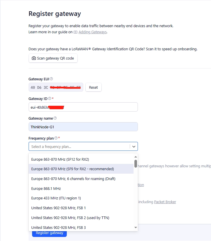
Gateway ID: Usually consists of letters (eui-“Gateway EUI”) (the ID must contain only lowercase letters, numbers, and dashes) Note that the letters in “Gateway EUI” must be converted to lowercase .
Gateway Name: The name of the Gateway Gateway name: Name of the gateway Frequency plan: Select the appropriate frequency according to your gateway version
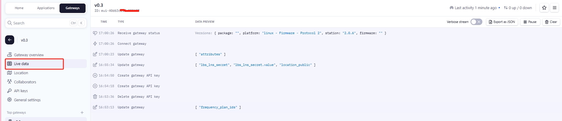
After successful registration, you can view the gateway in the overview.

Gateway Configuration
To configure the gateway via the Web UI, see Quick Start to log in to the local console first.
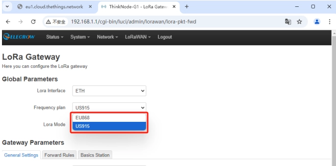
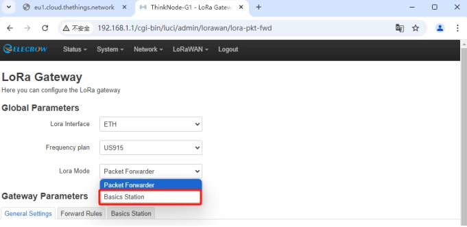
Step 1: LoRa Network Setup
Click LoRaWAN in the Luci interface, navigate to LoRa Gateway interface

Step 2: Set Mode to Packet Forward
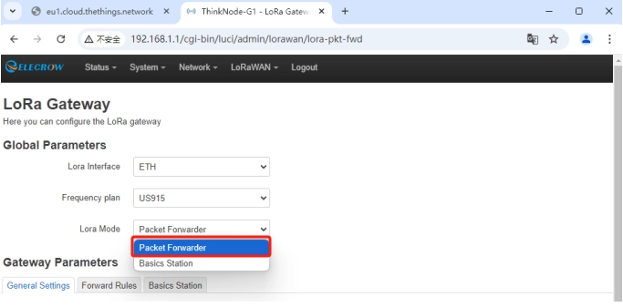
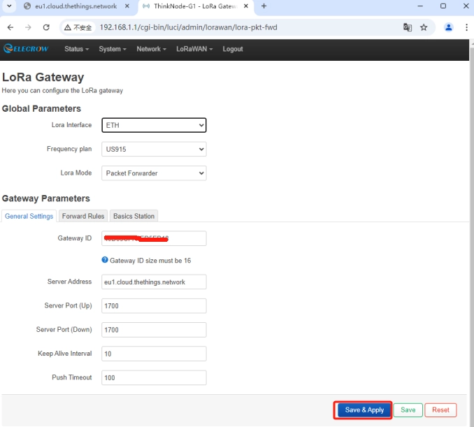
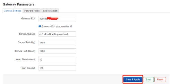
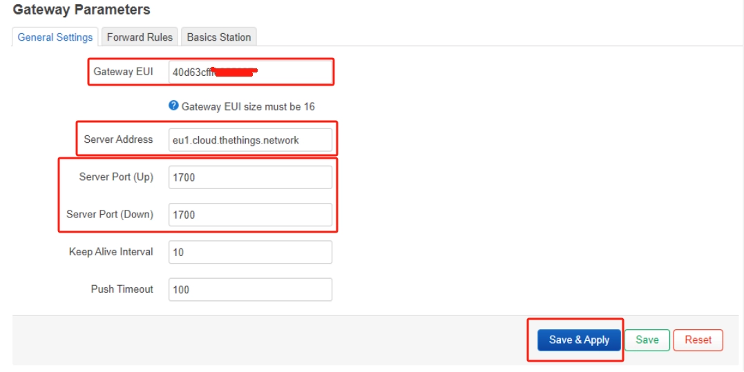
Step 3: Packet Forwarder Setting
- Gateway EUI: It will automatically get the EUI of the connected gateway.
- Server Address: For Semtech UDP Packet Forwarder, please use “server-address” ‘server-address’ is the address where The Things Stack is deployed.
- Server Port (Up/Down): The uplink and downlink ports are usually 1700. The other settings can be left at the default values or can be changed according to your requirements.
Step 4: Channel Plan Setting
Select Region and Frequency plan according to actual selection.
After setting, click Save & Apply
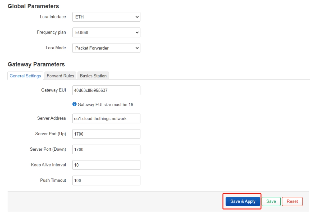
Wait for the gateway to reboot, now the gateway is connected to TTN as Packet Forward.
Connecting via Basic Station
The LoRa Basics™ Station is the preferred way to connect the gateway to The Things Stack. TTN supports TLS Server Authentication and Client token, which requires a trust file and key file to configure the gateway to connect it successfully to the network. You can use an LNS or CUPS server to connect the gateway to the TTN.
LoRaWAN Network Server (LNS) The LNS establishes a data connection between the LoRa Basics™ Station gateway and the network server (in this case, The Things Stack). ® LoRa uplink and downlink frames are exchanged over this data connection. The LNS protocol is required to send and receive LoRaWAN data.
Configuration and Update Server (CUPS)
CUPS allows Network Server to remotely configure the gateway and update the gateway firmware. CUPS is not required to send and receive LoRaWAN data, but it can greatly simplify gateway management. Configuring CUPS also automatically retrieves LNS credentials and configures LNS on your gateway.
Connecting to the Gateway through an LNS Server
TTN Configuration
Step 1: Register the Gateway - (Refer to Steps 1-2 in Packet Forwarder Connection - TTN Configuration - Registering the Gateway)
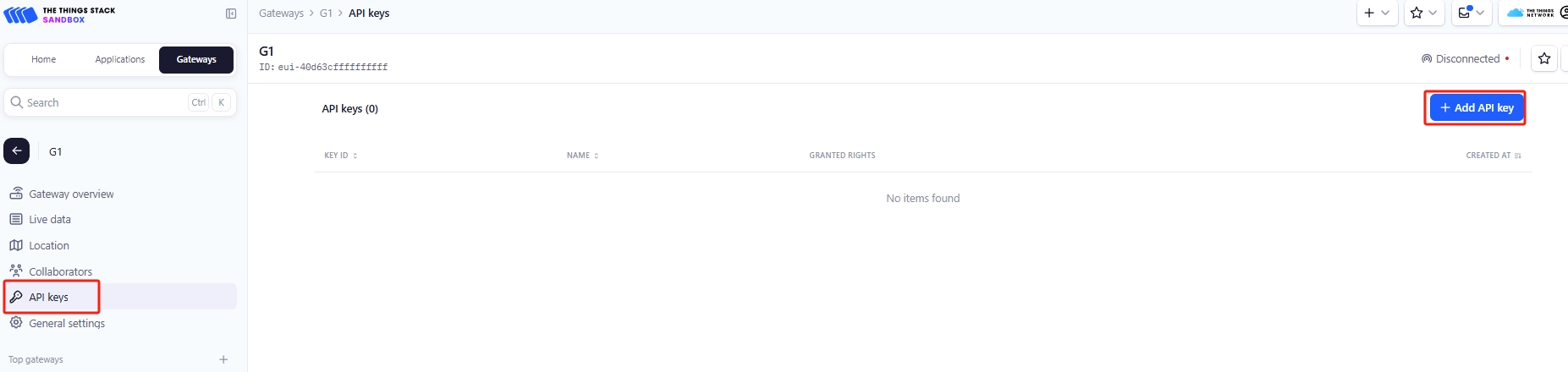
Step 2: To create an LNS-API key, navigate to API keys from the Overview page of the registered gateway.
On the API key page, click + Add API key.
Step 3: In the Name field, enter a key name (for example - LNS_key). Select Grant individual rights, and then select Link as Gateway to a Gateway Server for traffic exchange, i.e. read uplink and write downlink.
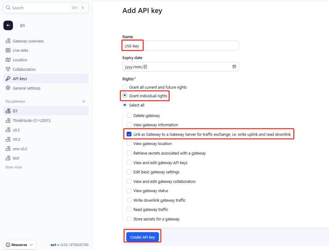
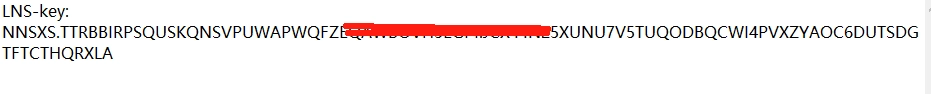
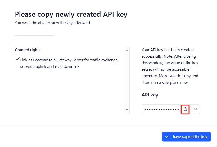
Step 4: Click Create API key to generate the key, a window will pop up as shown below prompting to copy the generated key.

Note:
Be sure to copy the key and save it in a .txt file (or other file), otherwise you will not be able to view or copy the key later.
Then click I have copied the key to complete the API key creation.
Gateway Configuration
To configure the gateway through the Web UI, see Quick Start to log into the local console first.
Step 1: LoRa Network Setup
Click LoRaWAN in the Luci UI and navigate to the LoRa Gateway interface

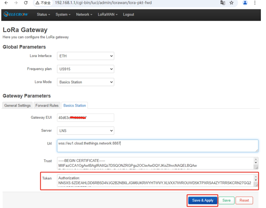
Step 2: Set Mode to Basics Station
Step 3: Basics Station Setting:
- Gateway EUI: It will automatically get the EUI of the connected gateway.
- Server: Select LNS Server.
- URL: LNS uses URI: wss://eu1.cloud.thethings.network:8887
4.Trust (CA Certificate) - Click choose file to upload the Let's Encrypt ISRG ROOT X1 Trust certificate, view or download the certificate https://www.thethingsindustries.com/docs/gateways/concepts/lora-basics-station/lns/。
5.Token - Duplicated API Keys: <Your_API_Key
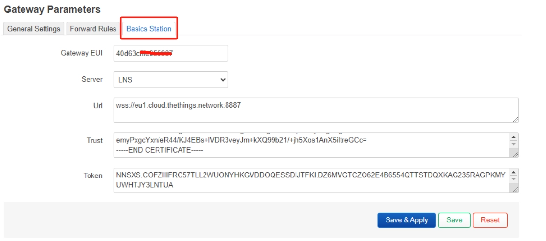
Duplicate API Keys (LNS-key).
The other settings can be left as default or changed according to your requirements.
Step 4: Channel Plan Settings
Depending on the actual selection, select Region and Frequency plan.

Step 5: Click Save Changes to save the changes.
Wait for the gateway to reboot, now the gateway is connected to TTN as a Basics Station (LNS).
Connecting the Gateway through a CUPS Server
TTN Configuration
Step 1: Since CUPS automatically configures LNS, you will need to generate two API keys - one for CUPS and one for LNS. To generate the key file, navigate to API keys from the Overview page of the registered gateway (in the TTS console). on the API key page, click +. Add API key.

Step 2: In the Name field, enter the name of the LNS key (for example - Ins_key). Select Grant individual rights and then select Link as Gateway to a Gateway Server for traffic exchange, i.e. read uplink and write downlink.

Step 3: Click Create API key to generate the key, a window will pop up as shown below prompting to copy the generated key.
Note:
Be sure to copy the key and save it in a .txt file (or other file), otherwise you will not be able to view or copy the key later.
Click I have copied the key to continue generating the LNS key.
Step 4: Click +Add API key again and in the Name field, enter the name of the CUPS key (for example - CUPS_key). Select Grant individual rights and select the following permissions:
- View gateway information
- Retrieve secrets associated with a gateway
- Edit basic gateway settings
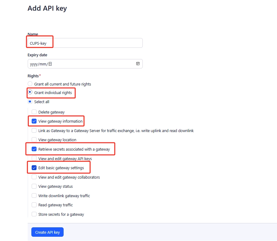
Step 5: After clicking Create API key to create the key, copy the key.
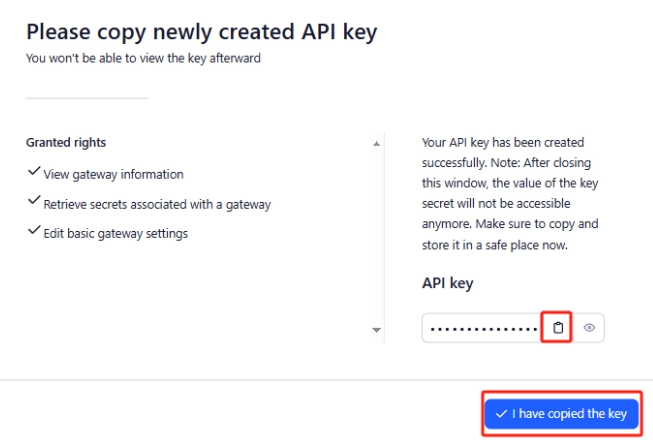
Note:
Be sure to copy the key and save it in a .txt file (or other file), otherwise you will not be able to view or copy the key later.
Click I have copied the key to continue.
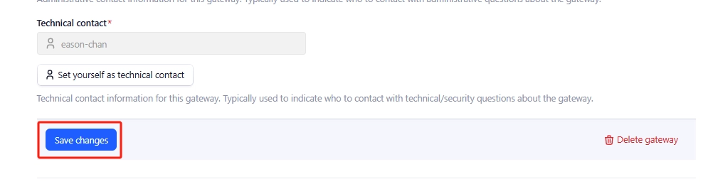
Step 6: Click General settings and scroll down to LoRa Basics Station LNS Authentication Key and paste the LNS key you copied in Step 3 there.
Copy the LNS key as shown below: :*Note that you have to select “Enabled” for Require authenticated connection.*
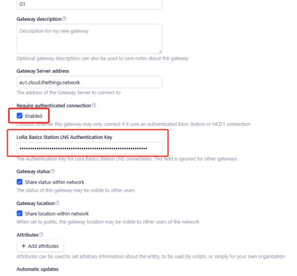
Step 7: Scroll down and click Save changes to save the settings.
Gateway Configuration
To configure the gateway via the Web UI, please check Quick Start to log into the local console first.
Step 1: LoRa Network Setup
Click LoRaWAN in the Luci UI and navigate to the LoRa Gateway interface

Click LoRaWAN in the Luci UI and navigate to the LoRa Gateway interface

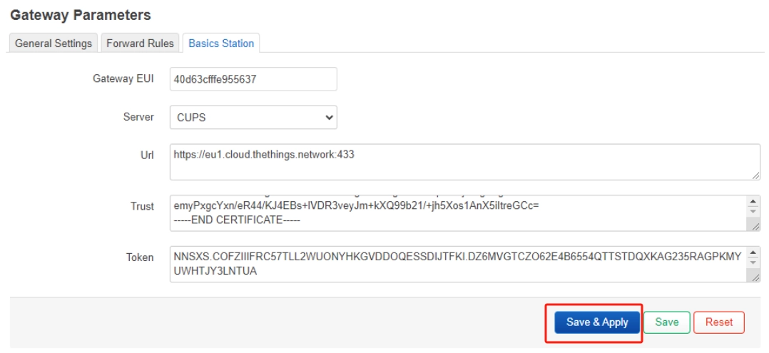
Step 3: Basics Station Setting:
- Gateway EUI: It will automatically get the EUI of the connected gateway.
- Server: Select CUPS Server.
- URL: CUPS uses URI: https://eu1.cloud.thethings.network:443
- Trust (CA Certificate) - Click choose file to upload Let's Encrypt ISRG ROOT X1 Trust certificate to view or download the certificate https://www.thethingsindustries.com/docs/gateways/concepts/lora-basics-station/lns/。
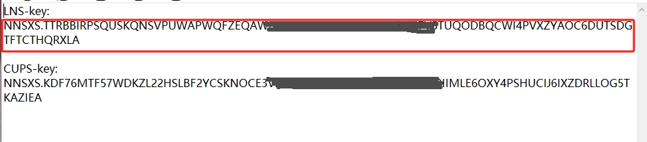
- Token - Duplicated API Keys: <Your_API_Key

Duplicated API Keys(CUPS-key)

Copy it as shown below::
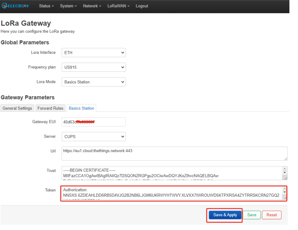
Step 4: Channel Plan Settings
Depending on the actual selection, select Region and Frequency plan.

Step 5: Click Save Changes to save the changes.

Wait for the gateway to reboot, now the gateway is connected to the TTN as a Basics Station (CUPS).

Creating TTN Node Applications
Step 1: Log in to your registered TTN account, in the TTN server interface, click Applications.
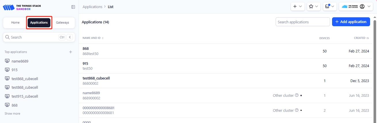
Step 2: Click Add applications, start to add node applications, enter the Applications ID, Applications name, and then click Create applications.

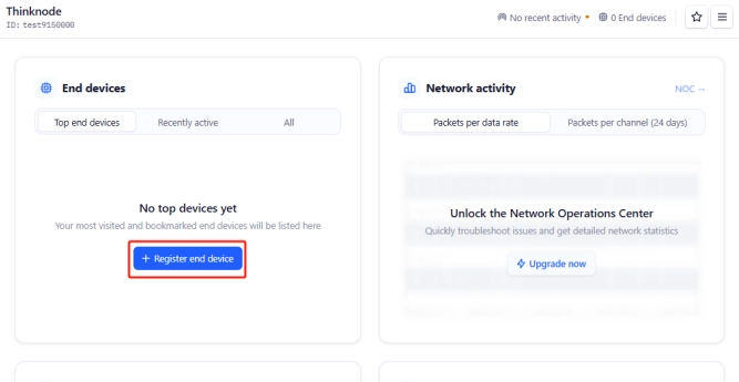
Step 3: Enter the application overview page, click “Register end device” in the lower right corner to register a new device in TTN platform.
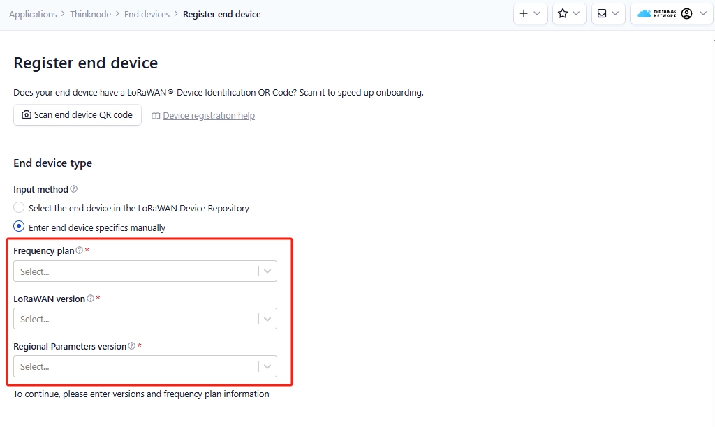
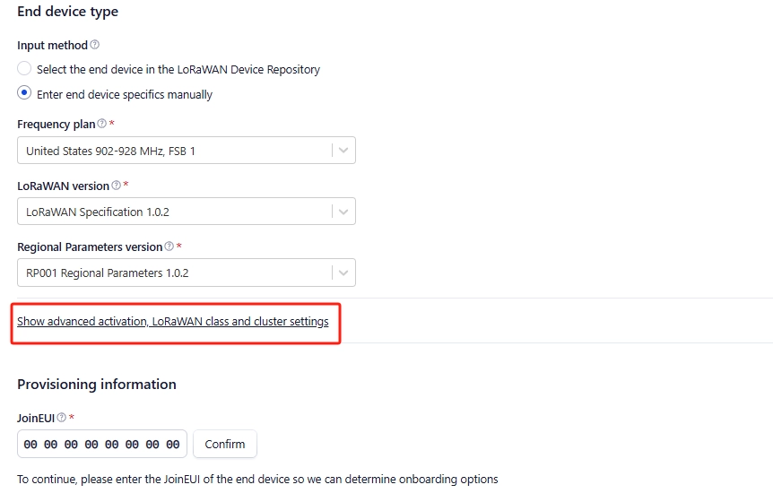
Step 4: In the “Register end device” page, click Enter end device specifics manually option.

Step 5: Set the Frequency plan, LoRaWAN version and Regional Parameters version to JoinEUI (APPEUI).
Note: JoinEUI means AppEUI.
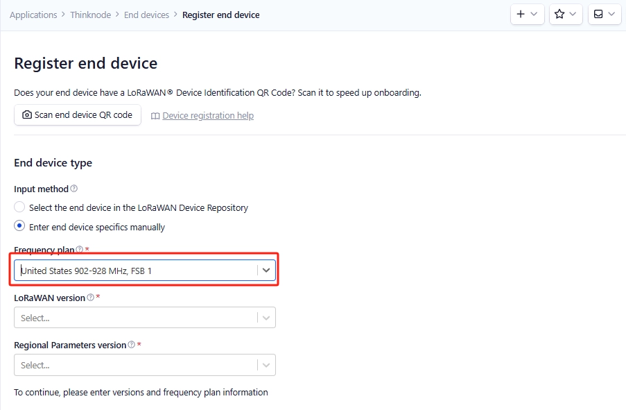
Set the Frequency plan,note that the band range should be consistent with the gateway used.
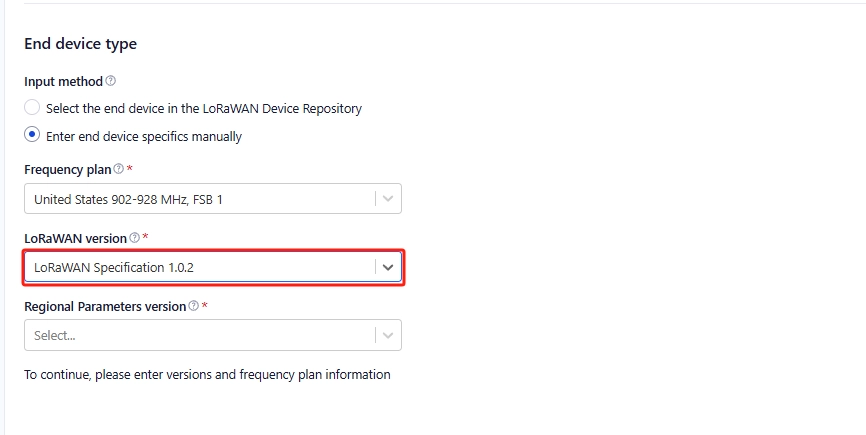
Set LoRaWAN version
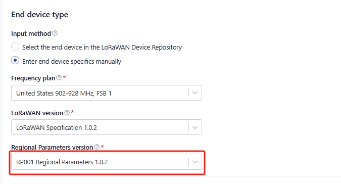
Set the Regional Parameters version
Set JoinEUI (APPEUI).
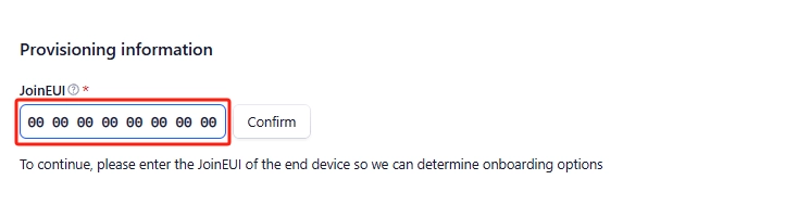
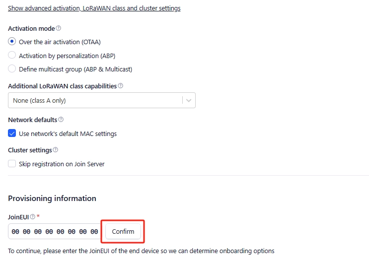
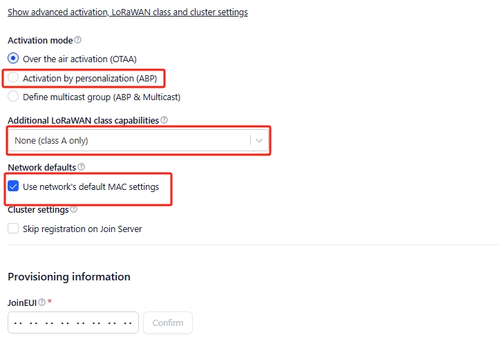
Step 6: Click Show advanced activation, LoRaWAN class and cluster settings. Configure parameters such as activation mode and device operating mode.
activation mode is OTAA when
Configure to OTTA mode (i.e., default mode)
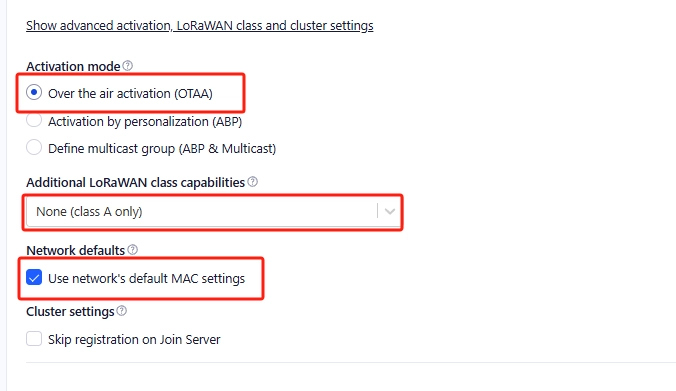
Then click Confirm
when the activation mode is ABP
Step 7: Configure the corresponding device parameters according to the activation mode selected above, as shown in the following figure:
when the activation mode is OTAA
Click Generate,automatically generate DevEUI.。

Click Generate to generate AppKey automatically.

Enter the End device ID
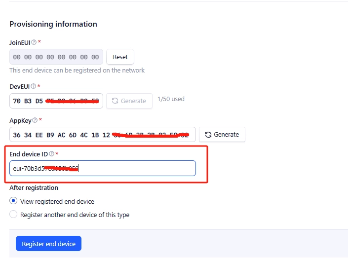
Click Register end device
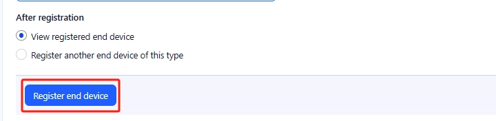
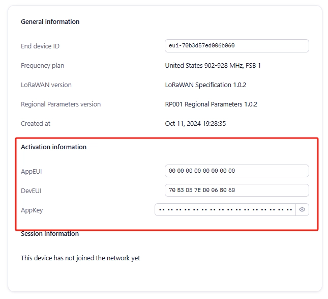
OTAA device is successfully registered.
activation mode is ABP
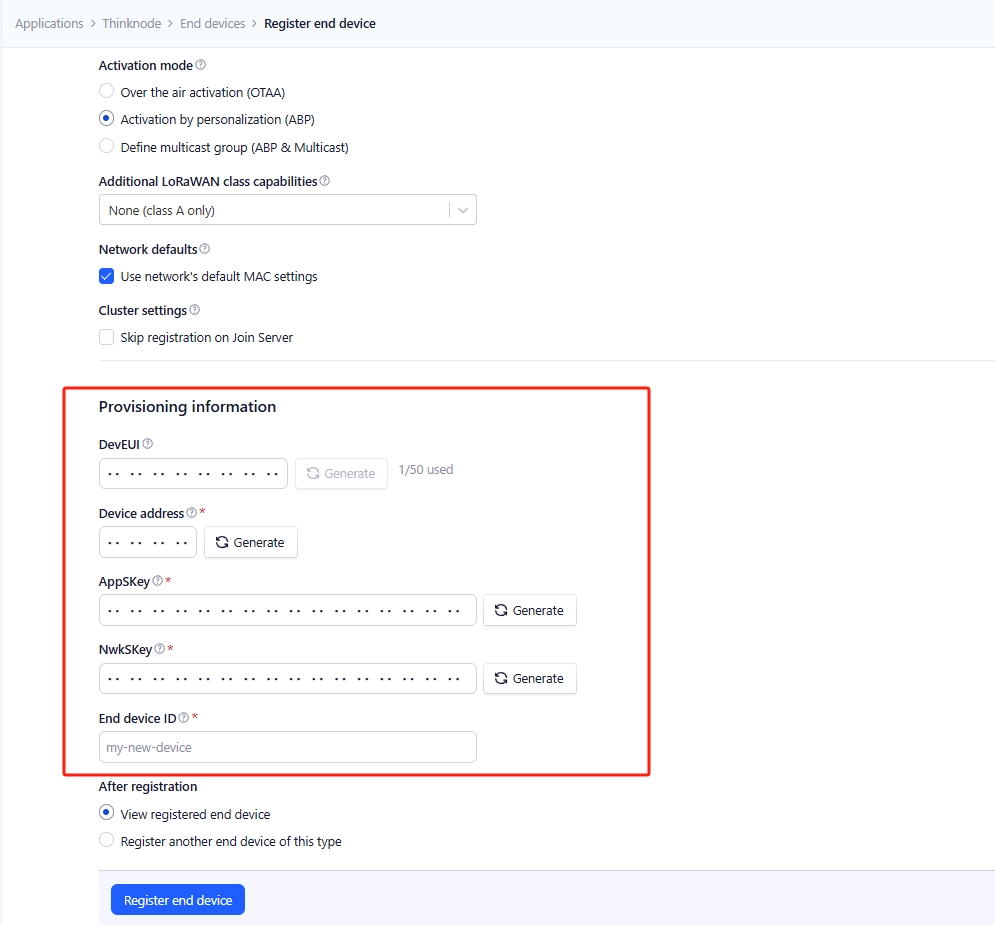
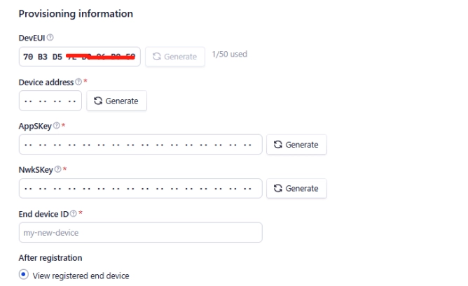
Enter DevEUI
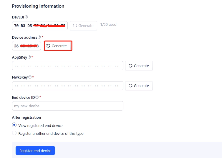
Click Generate to generate Device address automatically.
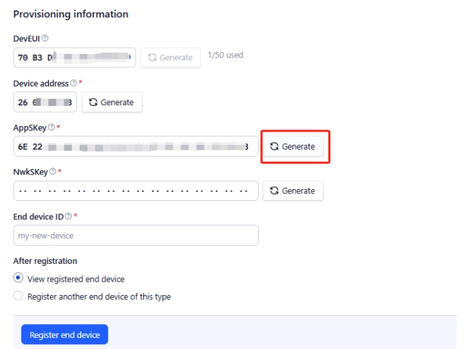
Click Generate to generate AppSkey automatically.
Click Generate to generate NwkSkey automatically.
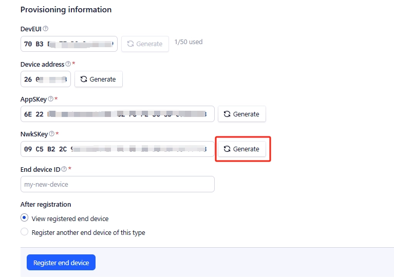
Enter the end device ID.
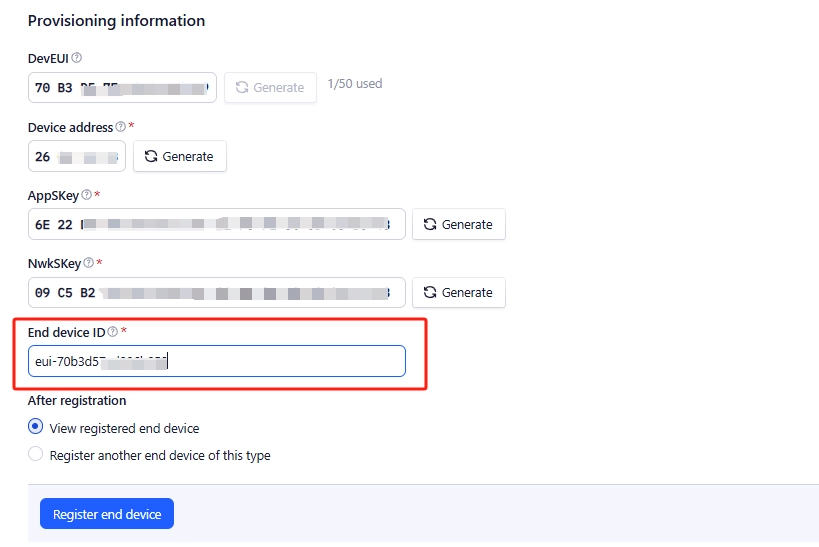
Click Register end device

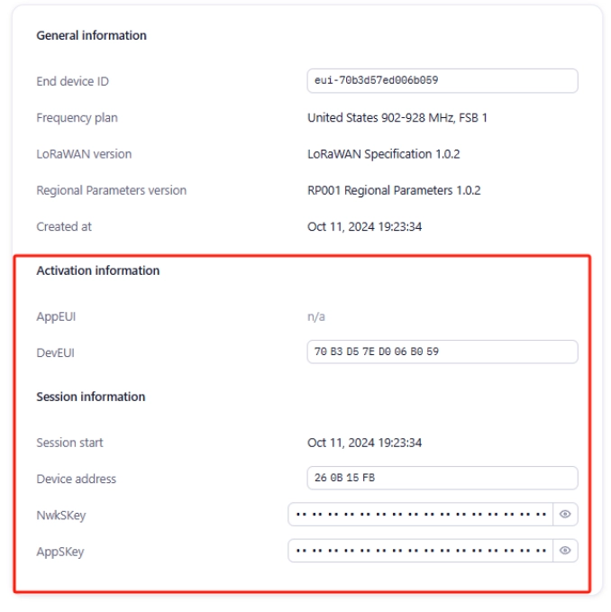
ABP device is successfully registered.
Communicate with the gateway through the created TTN application node and upload the node-gateway communication data to the TTN server
Prerequisites:
1. The gateway has been created in TTN, and the gateway has been connected and operated normally.
2. Node applications (OTAA/ABP) corresponding to the band range of the gateway have been created in TTN
hardware preparation
1.LR1262 Node Board
2.PC
3.TYPE-C data cable
4.Thinknode G1
software preparation
1.Configure LR1262 Node Board as USB-TTL communication software program “RP2040-USB-TTL.ino.rpipico.uf2”.
2.SSCOM serial port tool
Configure the LR1262 Node Board as USB-TTL communication mode (actually through the RP2040 comes with a USB interface, through the software program to realize the UART communication between the RP2040 and the LR1262).
Connect the LR1262 Node Board to the PC through the TYPE-C cable, and then first press the Connect the LR1262 Node Board with PC via TYPE-C cable, first press the “RP2040_BOOT” button on the LR1262 Node Board, and then press the ‘RST’ button, then a “RPI-XX” virtual USB flash disk will be popped up on the PC automatically. “Copy ”RP2040-USB-TTL.ino.rpipico.uf2“ to the ”RPI-XX" virtual USB flash disk and wait for the copying to complete. The LR1262 Node Board can be configured for USB-TTL communication.
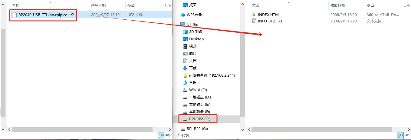
Note: After the program is burned, you need to power off the LR1262 Node Board, and then power on it again!
Through the SSCOM serial tool, send AT commands to configure the LR1262 Node Board as an OTAA/ABP node application established in the TTN, and through sending AT commands, join the LR1262 Node Board to the LoRaWAN network, complete the networking communication with the gateway, and upload the real-time node and gateway communication data between the node and the gateway is uploaded to the TTN server.
Use OTAA mode to join the LoRaWAN network (LR1262 Node Board uses the network entry mode by default)
Step 1: Open the SSCOM serial port tool in the Serial Port Assistant, select the USB COM port recognized by your computer, and then click “EXT”, as shown below.
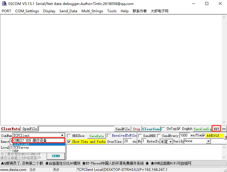
Step 2: Select and input the AT command information as follows on the extended interface of the serial port assistant:
(1) Serial port setting
1, baud rate: 9600 2, check the serial port carriage return line feed (2) Node access to the single-channel gateway configuration steps (send AT commands)
1, AT + RFS: clear the flash memory, every time you set up the access frequency band or re-entry, you have to send this command to clear the flash memory of the internal chip of the LR1262, otherwise it will affect the module. This instruction must be sent to clear the flash memory of the internal chip of LR1262 every time before setting the access band or re-entering the network.
2、AT+RESET:LR1262 node module reset instruction, you need to reset LR1262 module before re-entering the network.
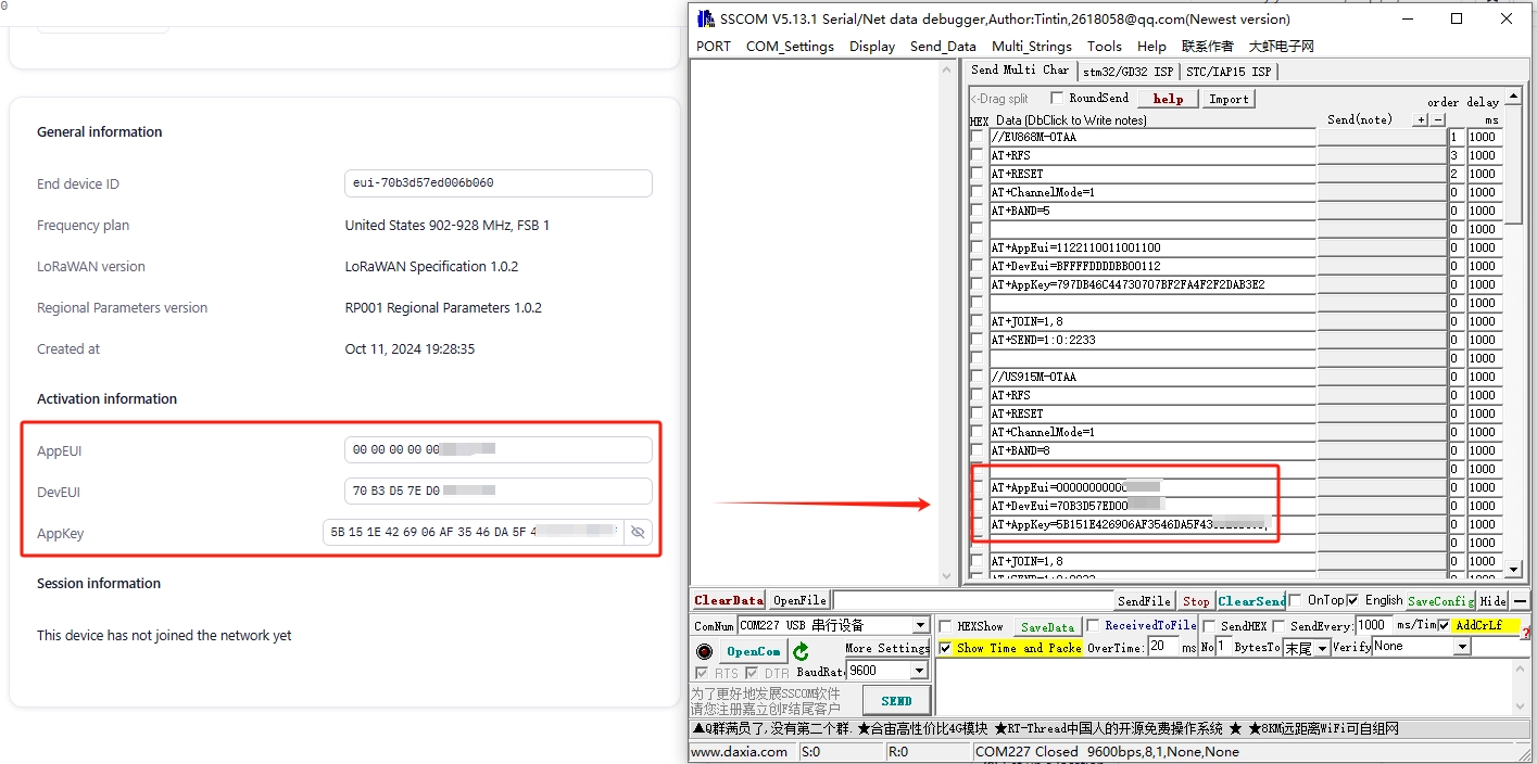
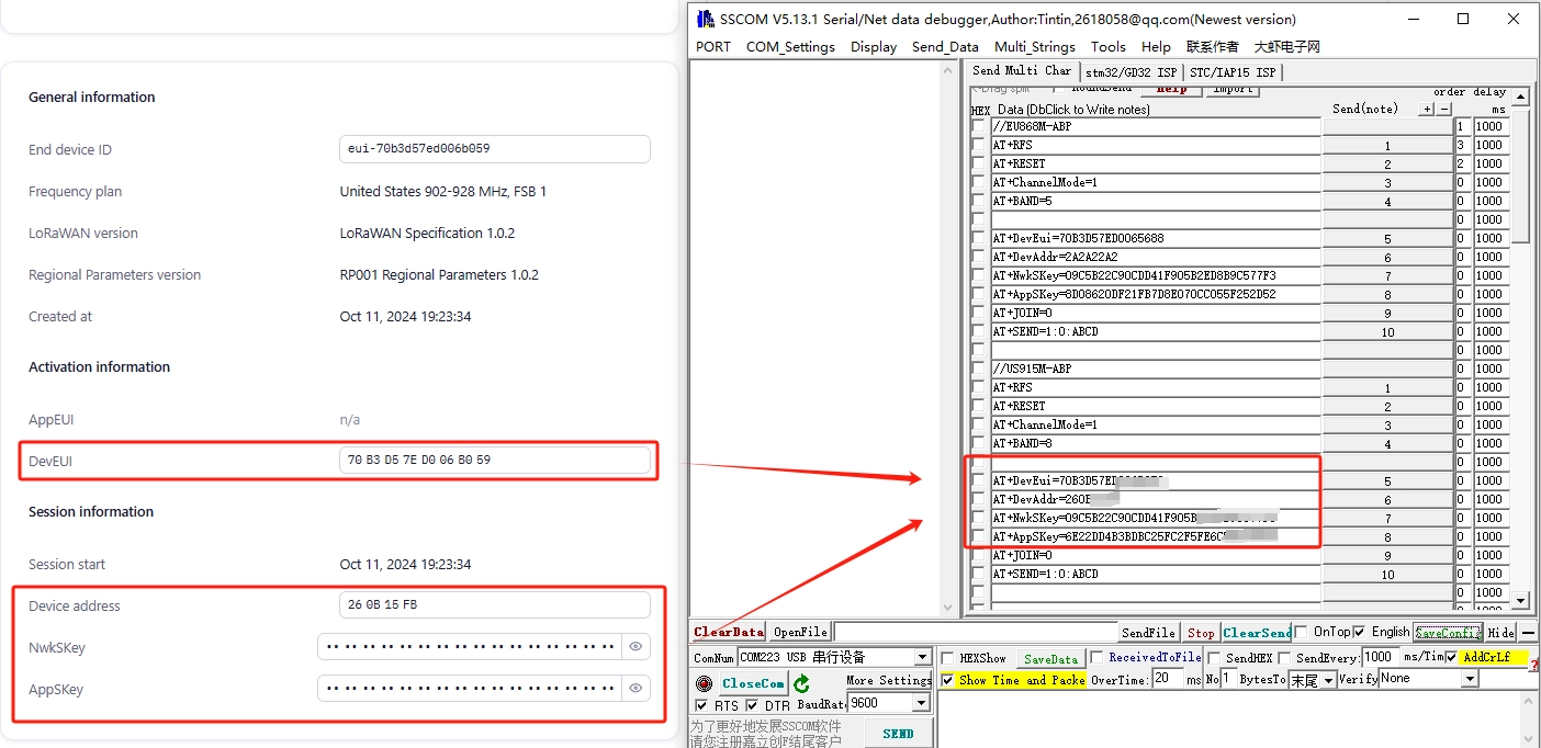
3、Select the node as single channel/multi-channel mode: AT+ChannelMode=0 (0 is single channel, 1 is multi-channel). 4, set the node into the network band: AT + BAND = 8, (5 for the 868 band, 8 for the 915 band, if it is a single-channel mode, the instruction is AT + BAND = 8,x (X for the selection of the band number 868 optional (0-2), 915 optional (0-7))). 5、Set node DevEui:AT+DevEui=70B3D57ED006****(Red part corresponds to TTN server) 6、Set node AppEui:AT+AppEui=220033001100****(Red part corresponds to TTN server) 7、Set node AppKey:AT+AppKey AppKey=F80013BC56A2B55375E467CBE5D9**** (the red part corresponds to the TTN server)

Here, it is important to note that DevEui, AppEui and AppKey should be replaced by DevEui, AppEui and AppKey in the application of the created OTAA node.
8, set the node to start netting: AT+JOIN=1,8 (parameter description: the first parameter is to select the netting mode, 0 is ABP mode, 1 is OTAA mode, the second parameter is the number of times to request netting cyclically in OTAA mode (1-8), ABP mode does not need to be cyclic). After sending this command, you need to wait for the node to enter the network, after the node enters the network successfully, then you can send the next command, as shown in the following figure: the information printed by the serial port tool after the successful entry:
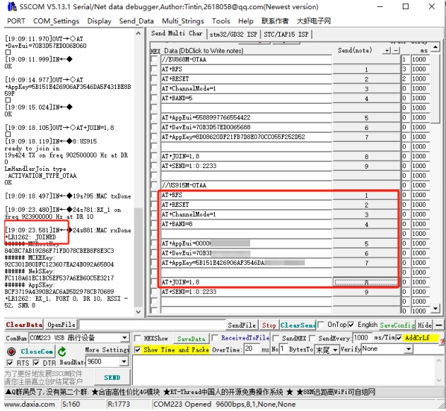
Input the above AT commands in Serial Assistant Expansion Interface, when you input the command “AT+JOIN=1,8”, “joined successfully” will appear, which means the LR1262 node module has been joined successfully!
9, start to send data: AT + SEND = 1:0:2233 (parameters: the last parameter for the data to be sent, and can only send an even number of data) SSCOM Serial Assistant commands are shown below:
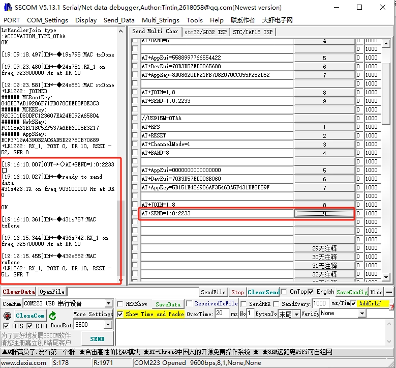
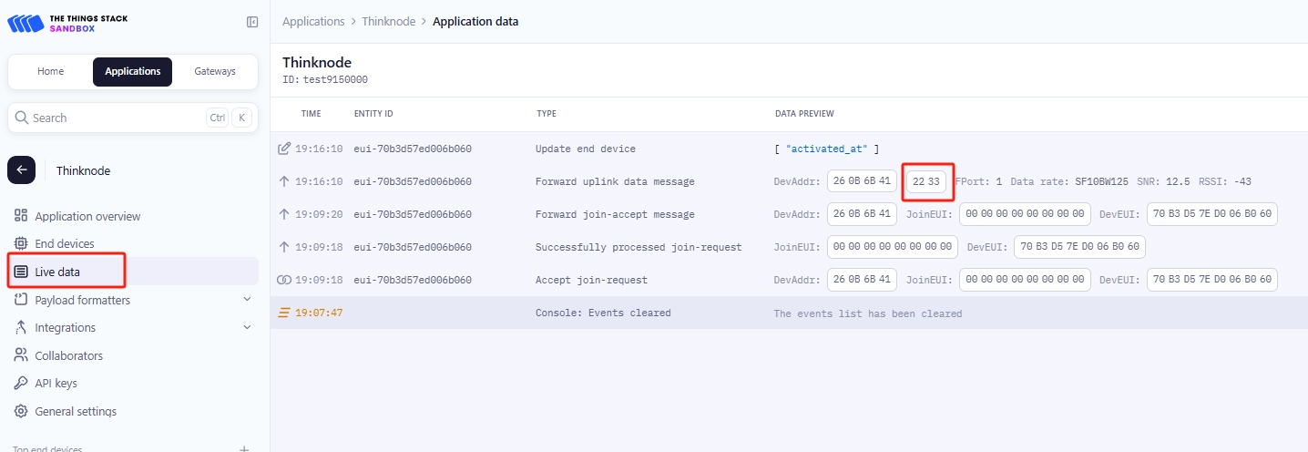
10, use “AT+SEND=1:0:2233” command to send data, in the background of the TTN server “Applications->Live data” you can see the node real-time sent data “2233”
Use ABP mode to join LoRaWAN network *
Step 1: Open the SSCOM serial port tool in the serial port assistant, select the USB COM port recognized by the computer, and click “EXT”, as shown in the following figure:

Step 2: Select and enter the AT command information as follows on the extended interface of the serial port assistant:
(1) Serial port setting 1, baud rate: 9600 2, check the serial port carriage return line feed (2) Node access to the single-channel gateway configuration steps (send AT commands) 1. AT + RFS: clear the flash memory, every time you set up the access frequency band or re-entry, you have to send this command to clear the flash memory of the internal chip of the LR1262, otherwise it will affect the module's performance. This instruction must be sent to clear the flash memory of the internal chip of LR1262 every time before setting the access band or re-entering the network. 2. AT+RESET:LR1262 node module reset instruction, you need to reset LR1262 module before re-entering the network. 3. Select the node as single channel/multi-channel mode: AT+ChannelMode=0 (0 is single channel, 1 is multi-channel). 4. set the node into the network band: AT + BAND = 8, (5 for the 868 band, 8 for the 915 band, if it is a single-channel mode, the instruction is AT + BAND = 8,x (X for the selection of the band number 868 optional (0-2), 915 optional (0-7))). 5. Set node DevEui:AT+DevEui=1A2A2A2A2A2C2C**** (Red part corresponds to TTN server) 6. Set node DevAddr:AT+DevAddr=2A2A22A2 (Red part corresponds to TTN server) 7. Set node NwkSKey:AT+NwkSKey= 25A252C25D2C2B6E2D3D3F2C2B3D**** (the red part corresponds to the TTN server) 8. Set the node AppSKey: AT+AppSKey=C2D2B2F2E3A2F1A35D1256216553**** (the red part corresponds to the TTN server)
Here, we should note that the Here, note that DevEui, DevAddr, NwkSKey, and AppSKey are replaced with DevEui, DevAddr, NwkSKey, and AppSKey in the application of the created ABP node.
8、8, set the node to start the network: AT + JOIN = 0 (parameter description: the first parameter is to select the network mode, 0 for ABP mode, 1 for OTAA mode, the second parameter is the number of times (1-8) of cyclic request to enter the network in the OTAA mode, no need to cycle in the ABP mode). After sending this command, you need to wait for the node to enter the network, after the node enters the network successfully, then you can send the next command, as shown in the following figure: the information printed by the serial port tool after the successful entry:

Input the above AT commands in Serial Assistant Expansion interface, when you input the command “AT+JOIN=0”, “joined successfully” will appear, which means the LR1262 node module has been joined successfully!
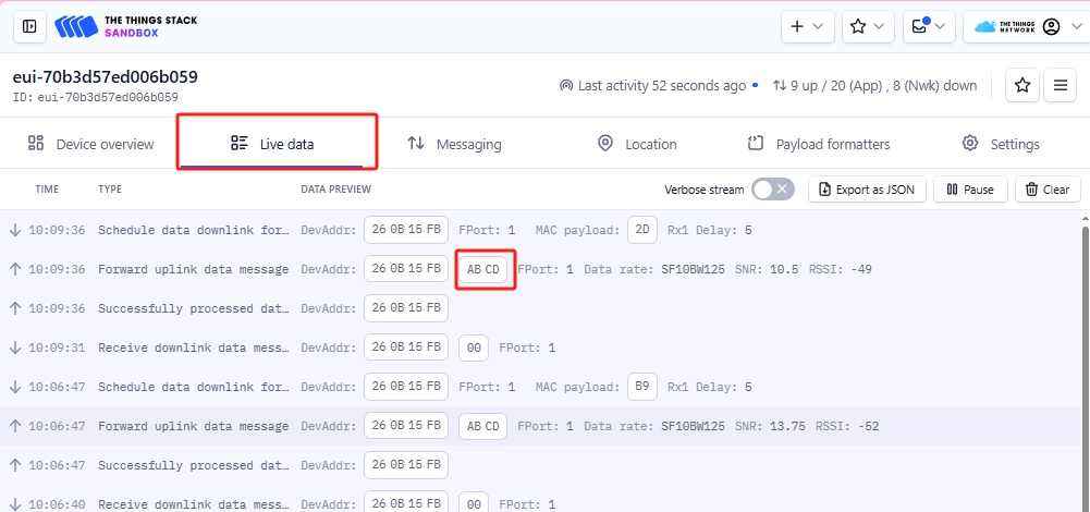
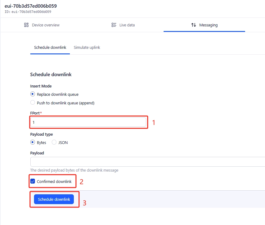
10, in ABP mode, before using AT+SEND instruction to send data, you need to set up the messaging of the ABP node that has just joined the network on the TTN server website.
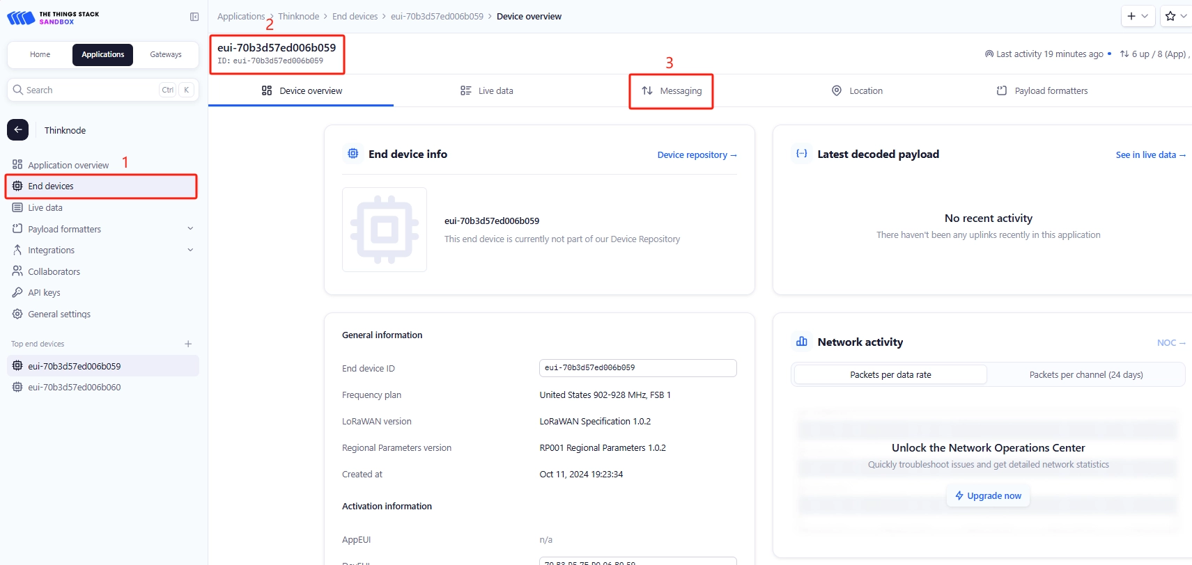
In the Messaging interface, enter FPort as 1, select Confirmed downlink, and then click Schedule downlink.
11, use “AT+SEND=1:0:ABCD” command to send data, in the background of TTN server “Applications->Live data” you can see the real-time data sent by the node. “ABCD”.