CrowPanel ESP32 Terminal SPI with ESP-IDF
Overview
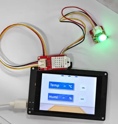
The example tutorial is an environmental monitoring project, demonstrate how to create a UI and use a Humidity&Temperature sensor to obtain the environment temperature and humidity and display it on the screen; and how to control the LED on and off by the buttons on the screen.
In this tutorial, we will show you how to design the UI with SquareLine Studio, and show you how to build a project on ESP-IDF.
Hardware Preparation
| ESP32 Terminal | Crowtail-AM2302 | Crowtail-LED |
|---|---|---|
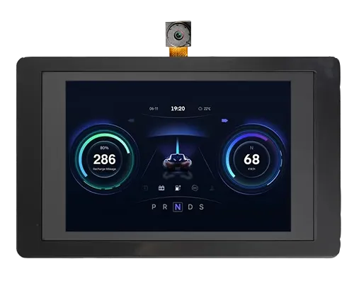 | 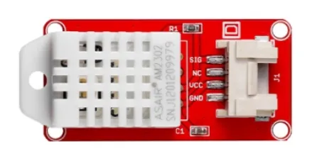 | 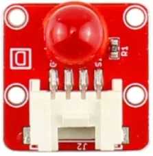 |
 |  |  |
Design UI file with SquareLine Studio
Get Started with SquareLine Studio
Please click the card below to learn how to download the SquareLine Studio, and how to export the demo UI file.
Design UI file with SquareLine Studio
Let's start learning how to create our own UI after getting an initial understanding of SquareLine Studio.
-
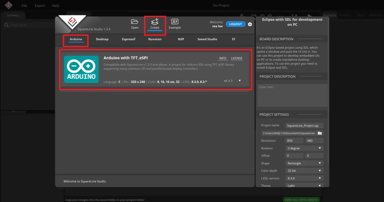
Open the SquareLine Studio and create a project. Select "Arduino"->"Arduino with TFT_eSPI".
Note:
When select the Arduino framwork, there's only one option "Arduino with TFT_eSPI". By choosing this, the squareline studio will generate a template code suitable for the TFT_eSPI library. However, squareline studio not only supports the TFT_eSPI library, it supports a variety of libraries to suit different hardware and application needs. For example, Adafruit_GFX library, LovyanGFX etc.
After using SLS to generate UI code, we then use different graphics libraries according to different hardware and modify the corresponding code to display the content you design.
-
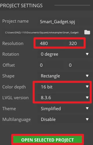
Set the name of the project, set the screen resolution to 480*320, set the color depth to 16bit, and keep other default settings. After setting, click CREATE to create the project.
-
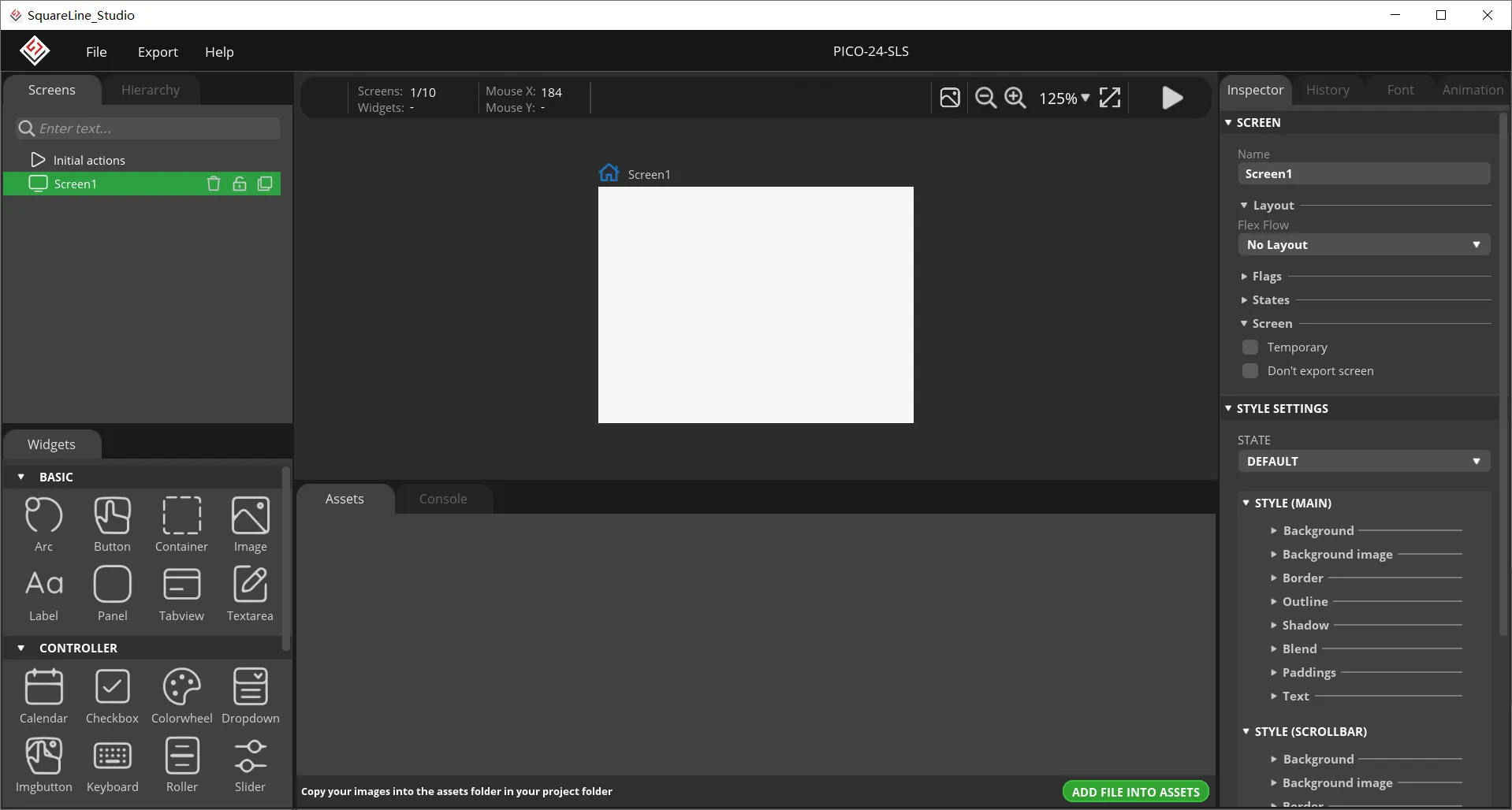
After creation, enter the following interface with a blank background.
-
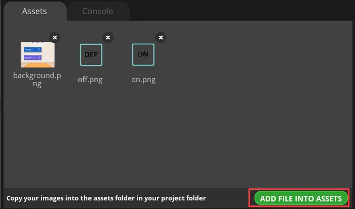
In the "Assets" area, click "ADD FILE TO ASSETS" to add custom images or icons.
Please click
 to download the custom images used in this tutorial.
Note:
Images only support PNG format. The pixels of the image need to be smaller than the pixel size of the screen used in your project. The size of each image should not exceed 100k, preferably within 30k, to provide a smooth display effect.
-
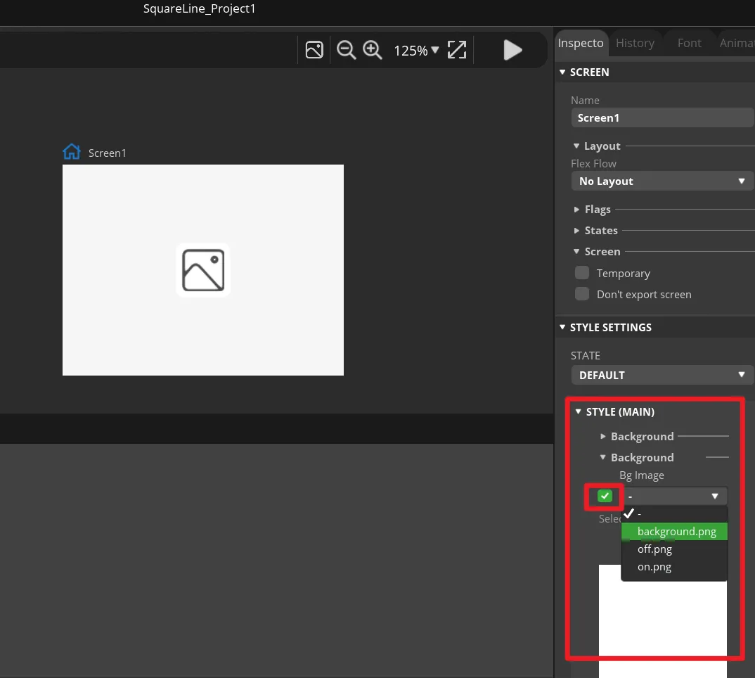
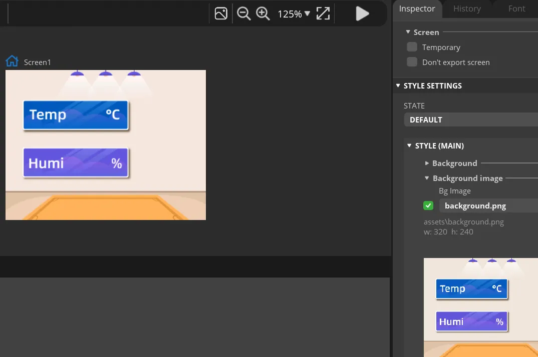
Add background.
Find "Inspector"->"STYLE SETTING", click to expand "STYLE(MAIN)", then click the 2nd "Background". Check the "Bg Image" and select the background image.
-
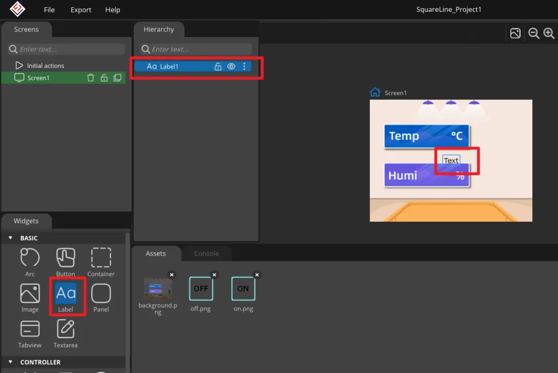
Add Label widget to display temperature and humidity.
Click "Label" in the "Widgets" area, and "Label1" will be added to the current Screen.
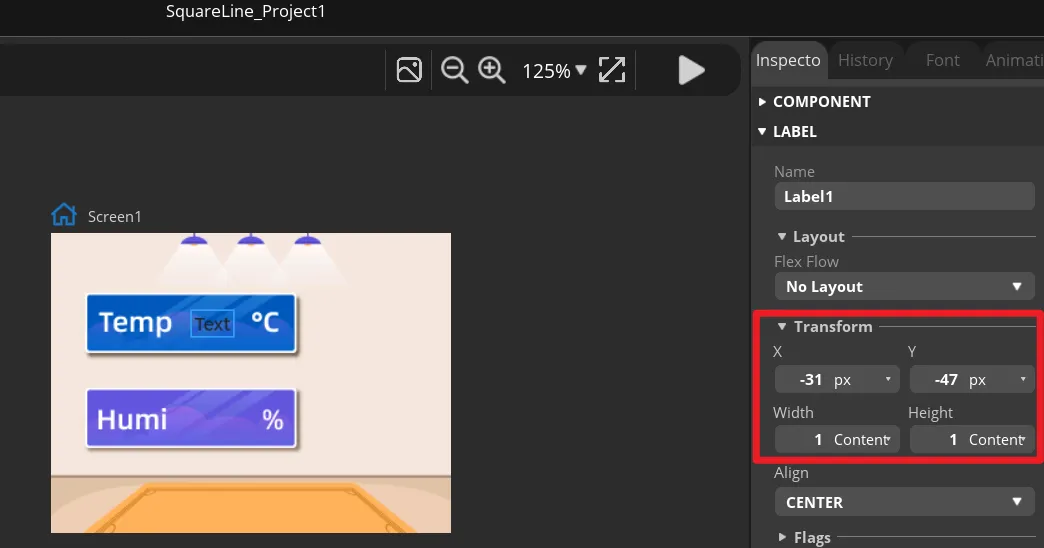
The position and size of the label can be adjusted by dragging the mouse. You can also directly enter numbers in the Inspector→LABEL→Transform to adjust.
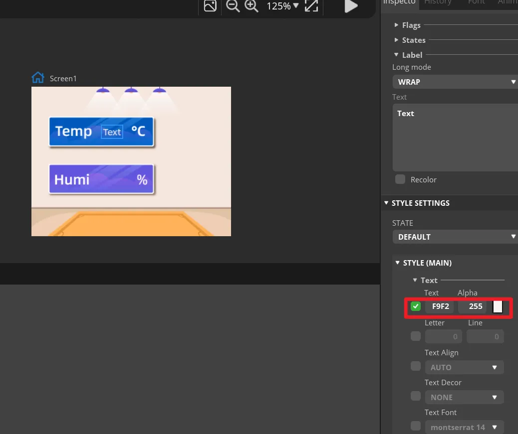
You can set the font color and other attributes in STYLE SETTING→STYLE(MAIN).
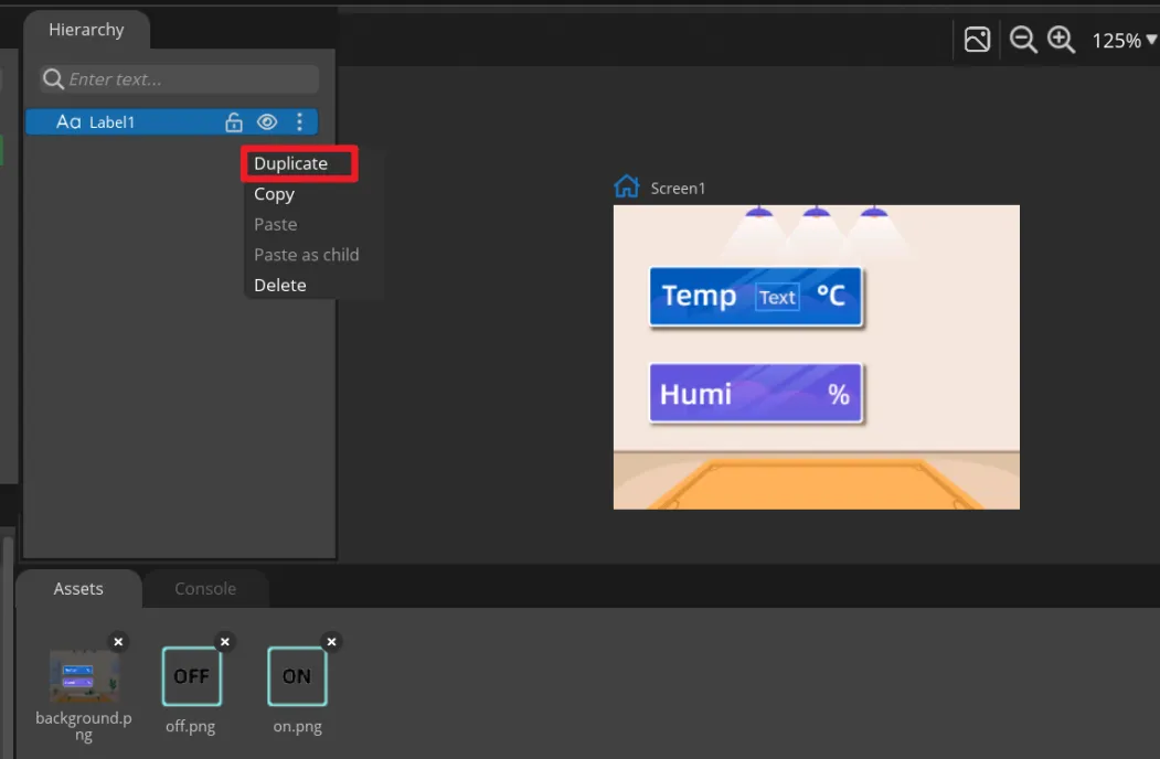
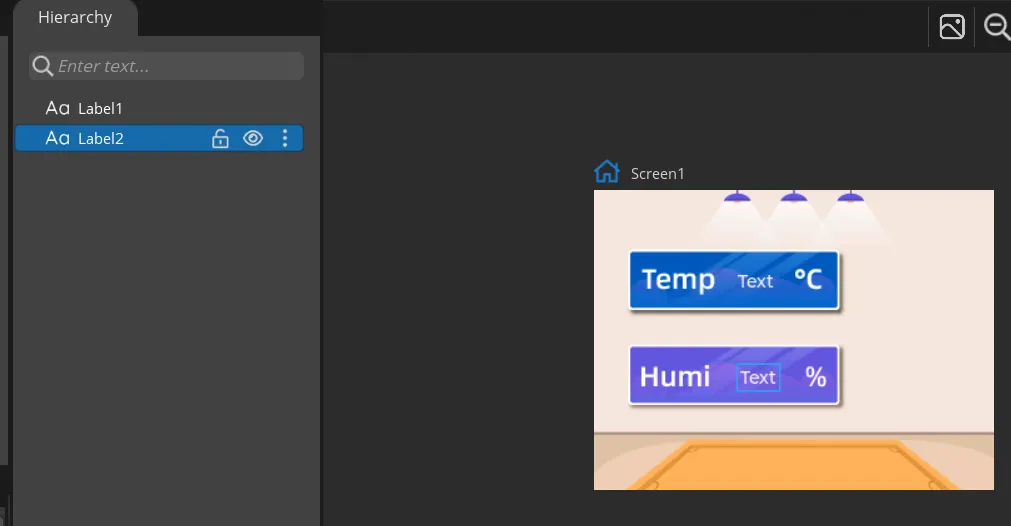
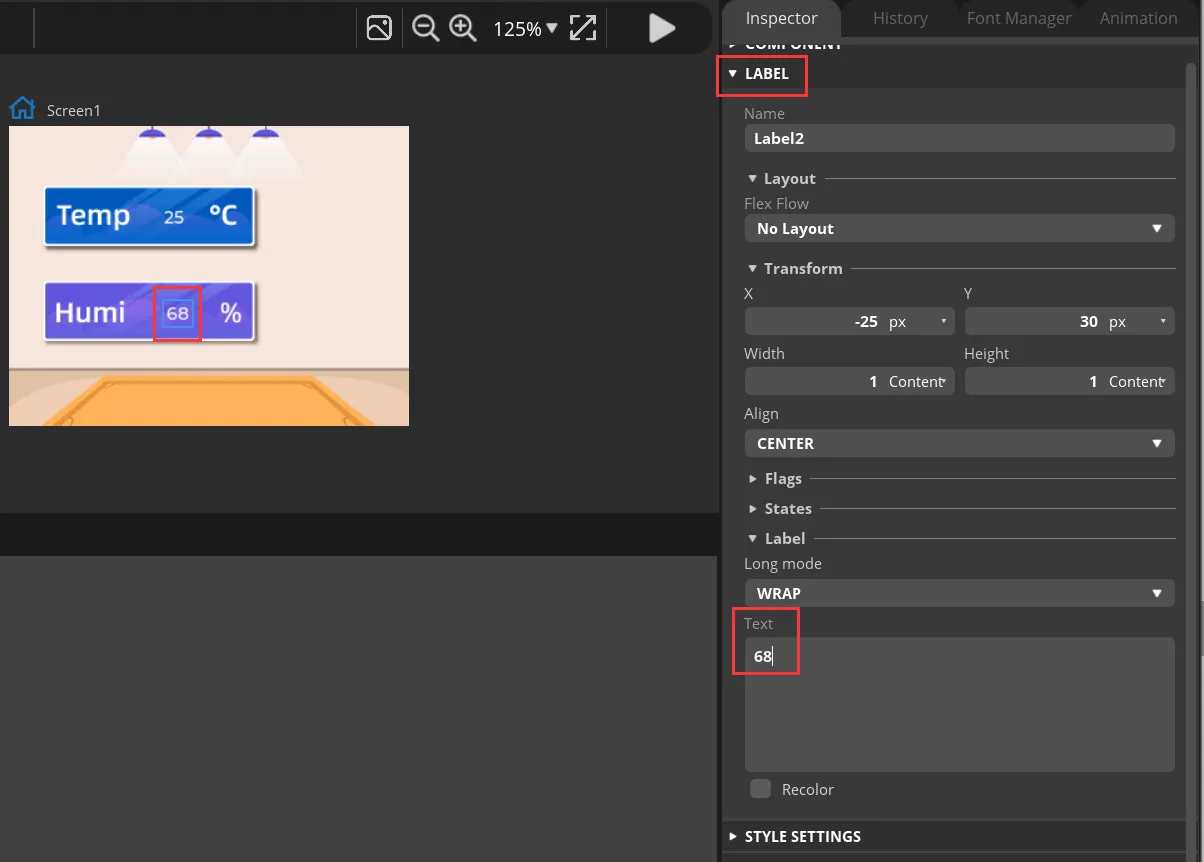
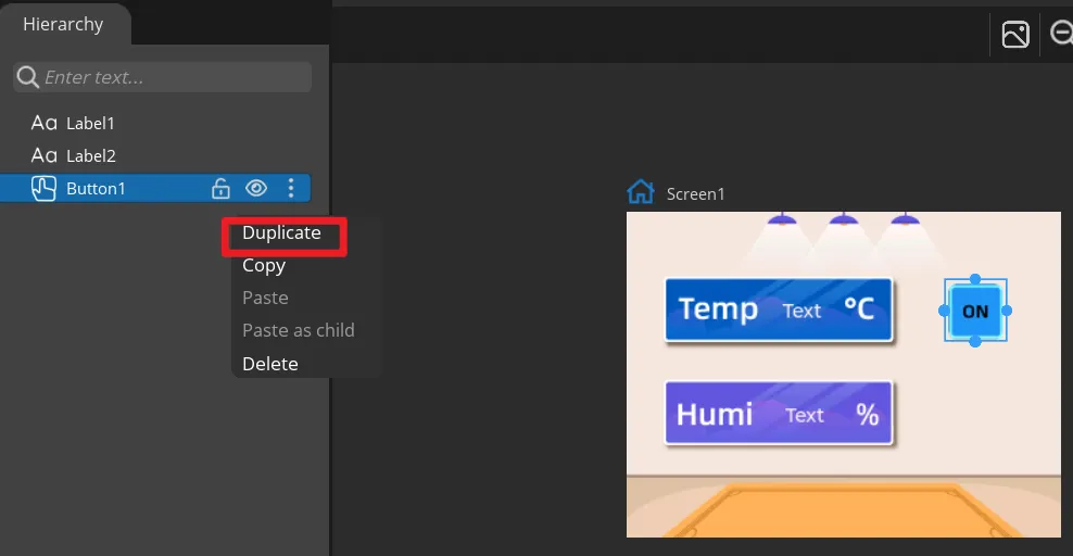
Add a Label2 to display the humidity value in the same way. You can also directly right-click the Label1 to duplicate it.
Then set different positions for the Label2.
Modify the text content to display a default value.
-
Add Button widget to control the LED.
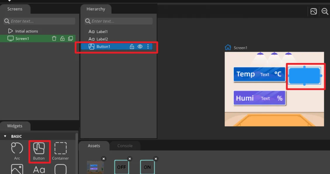
Click "Button" in the "Widgets" area, and "Button1" will be added to the current Screen.
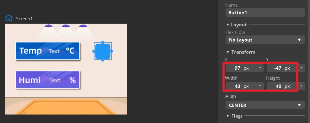
The position and size of the label can be adjusted by dragging the mouse. You can also directly enter numbers in the Inspector→BUTTON→Transform to adjust.
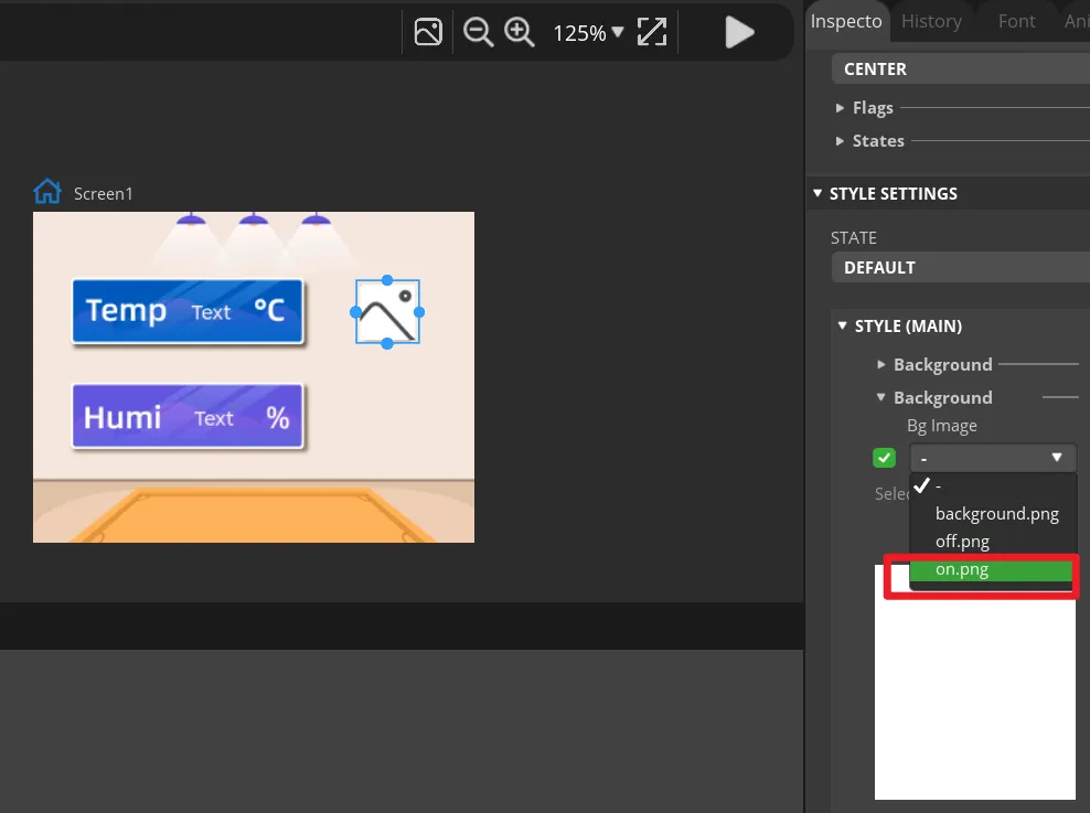
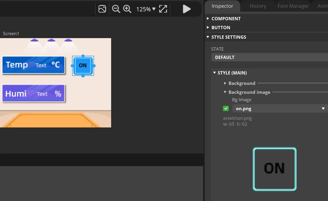
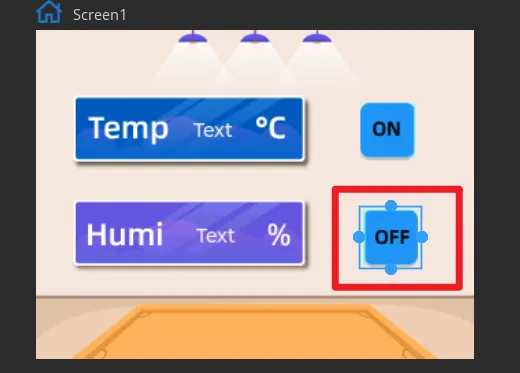
Add an identification symbol to the button. The button in this tutorial controls the LED switch, so you only need to mark the button "on" and "off". You can add LABEL widgets or add a background images to the button. This tutorial will demonstrate how to add a background image to a button.
Click the Button1, then find Inspector->STYLE SETTINGS ->STYLE(MAIN) ->Background, and select the image.
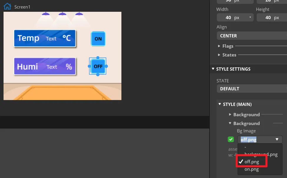
In the same way, duplicate a Button widget. And drag it to the corresponding position to modify different background image.
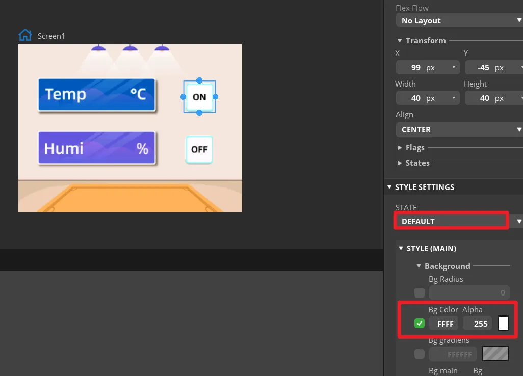
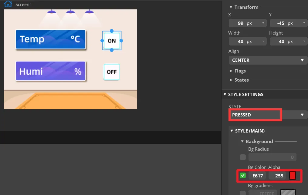
Set the status of the button to identify different states.
In "Inspector"->"STYLE SETTINGS"->"STATE", set display white background color by DEFAULT and red when on the PRESSED state.
Make the same settings for the "OFF" button.
-
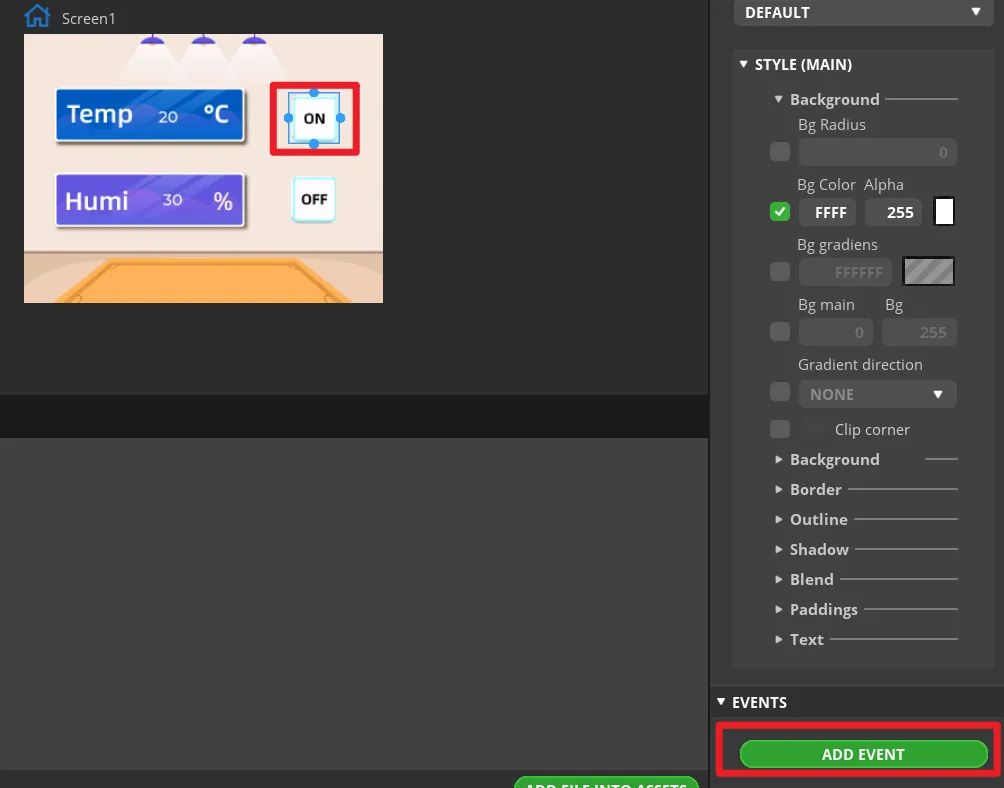
Add events to buttons.
Note: Because the button controls the on and off of the LED, we can add any event here to generate the code framework for the button event when exporting the UI file. We will modify the code of the button event to control the LED latter.
Select the button and click "ADD EVENT".
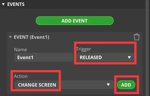
Select "released" as the trigger condition, select a trigger event in "Action". It will be modified in the generated program to achieve the LED control function.
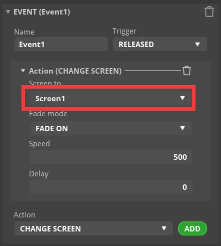
Complete the event. Here I choose to change the screen, and the screen to be switched is Screen1.
Add event to Button2 (OFF) in the same way.
-
Export UI files.
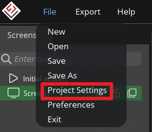
Click "File" -> "Project Settings" and make settings for the exported file.
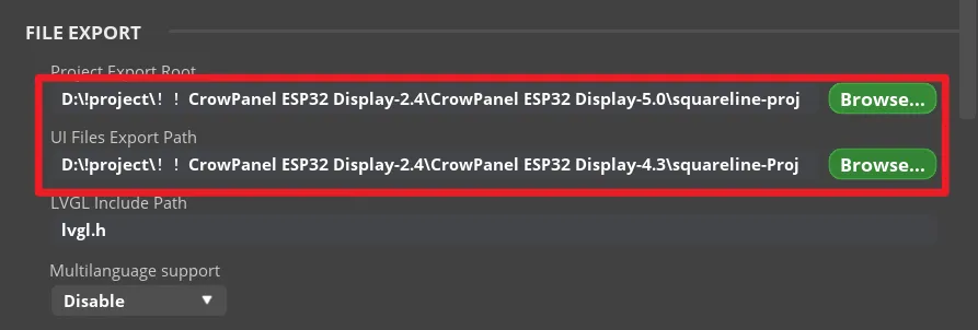
Set the export path of the file (set the path according to your own file).
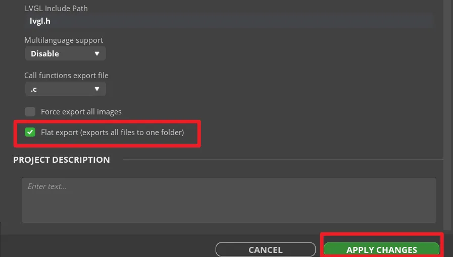
Fill in lvgl.h in LVGL Include Path. Check "Flat export(exports all files to one folder )".
Then click "APPLY CHANGES".
Tips: After selecting the flat export, the output files will be in the same folder, so that the output code does not need to modify the path in the program. If not, the output files will be classified and placed in different folders. The compiler may not be able to recognize different paths, which will cause some trouble. In this case, the user needs to modify it manually, so it is recommended to select all files to be output to the same folder.
Export UI files. The exported files will be in the path we set earlier.
You can click
 to download the export UI files we provided.
The UI file export is completed, and the button event function is also modified. Next we're going to learn about how to create a ESP-IDF project.
Create ESP-IDF Project
Get Started with ESP-IDF
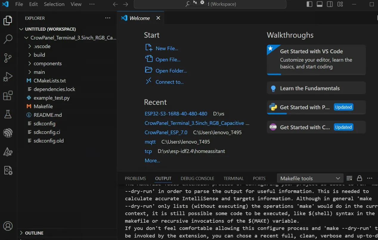
Please click the card below to learn how to install ESP-IDF. Create a blank project according to the "Get Started with ESP-IDF".
You can click  to download the complete project we provided. This project can be used directly. You can also create the project by following the tutorial.
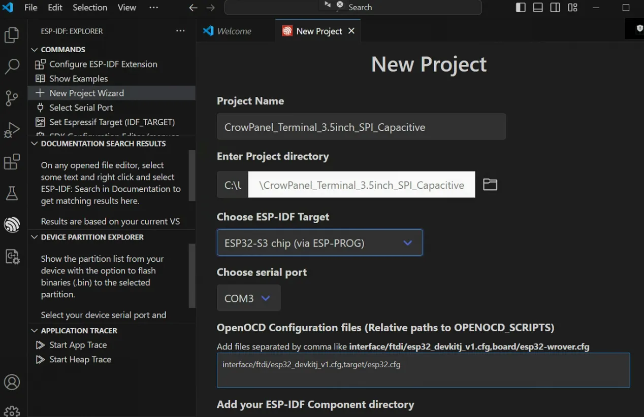
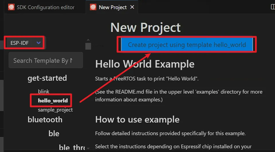
Create New Project
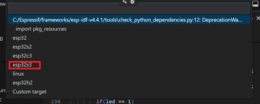
Create a new project according to the "Get Started with ESP-IDF". Choose "ESP320S3 chip(via ESP-PROG)" as ESP-IDF Target.
Add Libraries
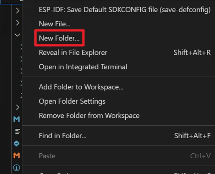
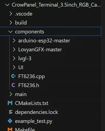
Create a new folder and name the folder 'components'. Add the libraries we provided to this folder.
Please click  to download the libraries we provided.
Configuring the UI File
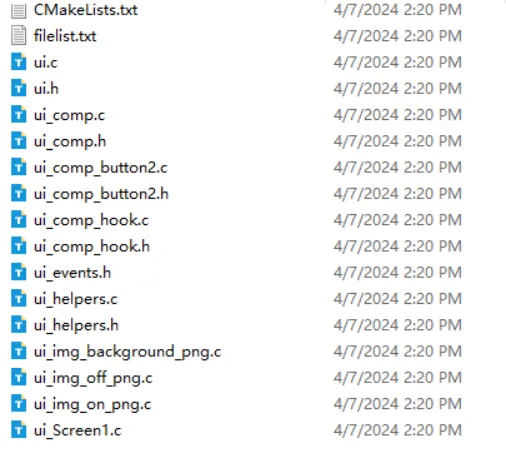
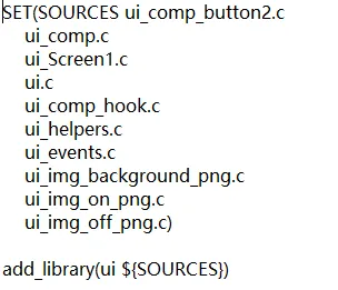
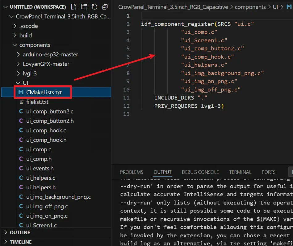
Modify CMakeLists.txt
Change from:
to:
idf_component_register(SRCS "ui.c"
            "ui_comp.c"
            "ui_Screen1.c"
            "ui_comp_button2.c"
            "ui_comp_hook.c"
            "ui_helpers.c"
            "ui_img_background_png.c"
            "ui_img_on_png.c"
            "ui_img_off_png.c"
    INCLUDE_DIRS "."
    PRIV_REQUIRES lvgl-3)
Modify the button event code.
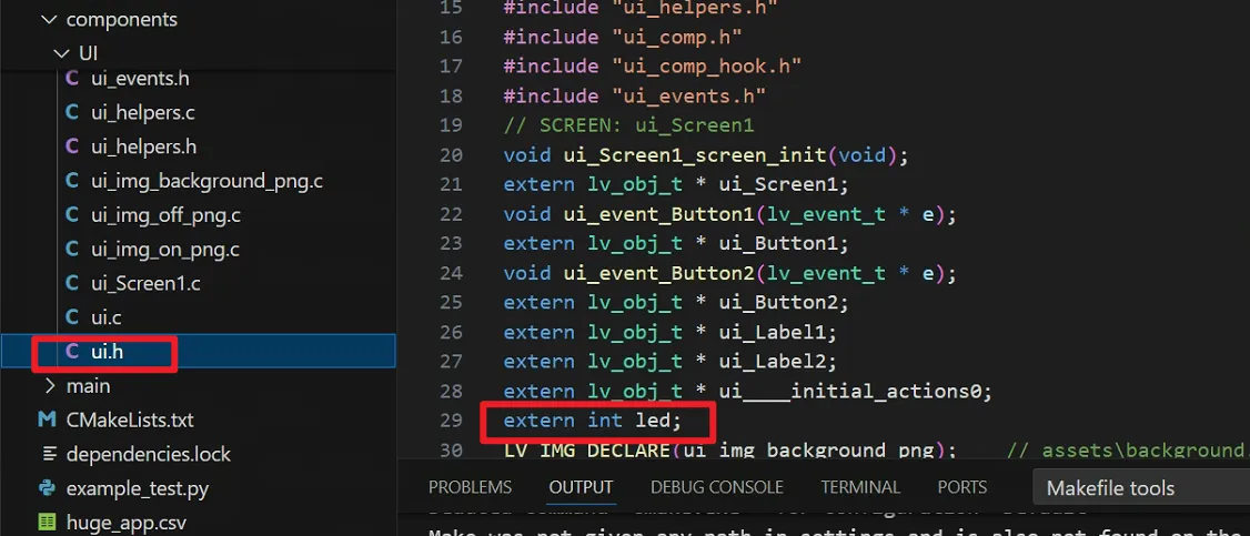
First, define a extern int led; in the ui.h file to store the status of the LED. The value of this variable is judged to control the on and off of the LED.
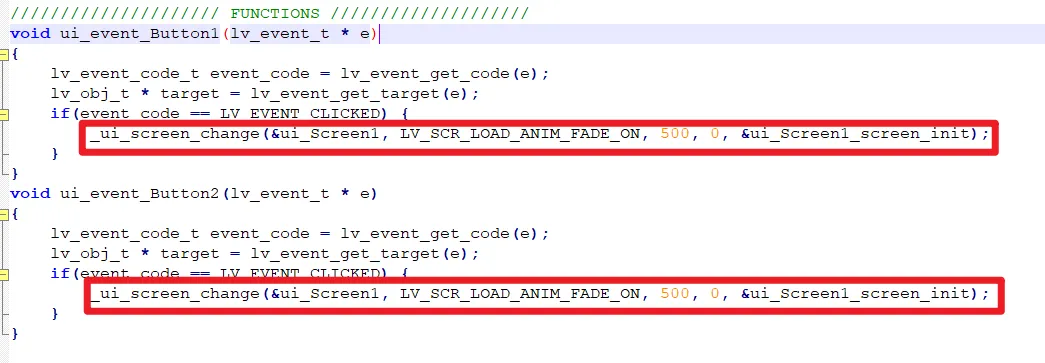
Then find "FUNCTION" in the ui.c file. Here is the corresponding code generated when we add events in SquareLine.
Comment out or delete the code circled in red in the picture above, add new code to assign a value to the LED variable.
- When button 1 (ON button) is pressed, set the LED value to 1.
- When button 2 (OFF button) is pressed, set the LED value to 0.
Setup main file
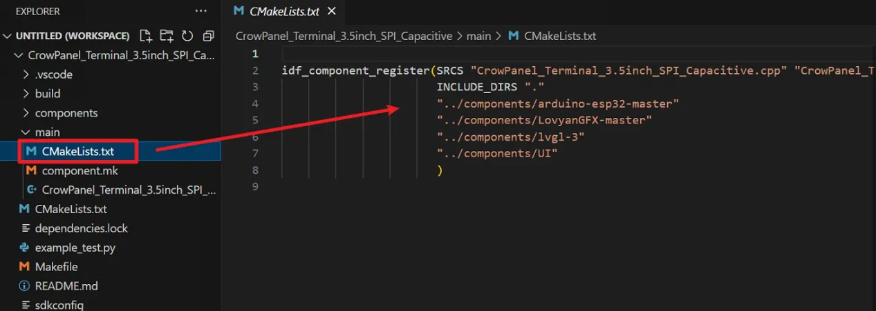
The CMakeList.txt file contains the Settings for the library. All required libraries should be included by directory address.
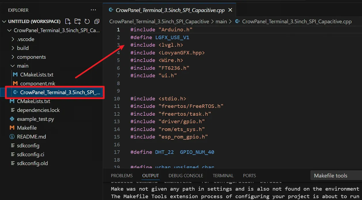
The main program is written in the .cpp file
#include "Arduino.h"
#define LGFX_USE_V1
#include <lvgl.h>
#include <LovyanGFX.hpp>
#include <Wire.h>
#include "FT6236.h"
#include "ui.h"


#include <stdio.h>
#include "freertos/FreeRTOS.h"
#include "freertos/task.h"
#include "driver/gpio.h"
#include "rom/ets_sys.h"
#include "esp_rom_gpio.h"

#define DHT_22  GPIO_NUM_40

#define uchar unsigned char
#define uint8 unsigned char
#define uint16 unsigned short

//Definition of temperature and humidity
uchar uchartemp;//COM function call, data transfer
float Humi,Temp;
//uchar ucharT_data_H,ucharT_data_L,ucharRH_data_H,ucharRH_data_L,ucharcheckdata;//验证过后传递数据
uchar ucharT_data_H_temp,ucharT_data_L_temp,ucharRH_data_H_temp,ucharRH_data_L_temp,ucharcheckdata_temp;
uchar ucharcomdata;//Stores data obtained by com


int led;
const int i2c_touch_addr = TOUCH_I2C_ADD;
#define get_pos ft6236_pos

#define LCD_MOSI 13
#define LCD_MISO 14 // 12
#define LCD_SCK 12
#define LCD_CS 3
#define LCD_RST -1 // 26
#define LCD_DC 42  // 33
#define LCD_BL 46


#define I2C_SDA 2
#define I2C_SCL 1

#define SD_MOSI 13
#define SD_MISO 14
#define SD_SCK 12
#define SD_CS 10

#define LED 11

static void InputInitial()
{
    esp_rom_gpio_pad_select_gpio(DHT_22);
    gpio_set_direction(DHT_22, GPIO_MODE_INPUT);
}
static void OutputHigh(void)//output 1
{
    esp_rom_gpio_pad_select_gpio(DHT_22);
    gpio_set_direction(DHT_22, GPIO_MODE_OUTPUT);
    gpio_set_level(DHT_22, 1);
}
static void OutputLow(void)//output 1
{
    esp_rom_gpio_pad_select_gpio(DHT_22);
    gpio_set_direction(DHT_22, GPIO_MODE_OUTPUT);
    gpio_set_level(DHT_22, 0);
}
static uint8 getData()//Read status
{
    return gpio_get_level(DHT_22);
}
//Read a byte of data
static void COM()
{
    uchar i;
    for (i=0;i<8;i++)
    {
        while(!getData())
            uchartemp=0;
        ets_delay_us(35);//delay 35us
        if(getData()==1)
            uchartemp=1;
        ucharcomdata <<= 1;
        ucharcomdata |= uchartemp;
        while(getData());
    }
}

void DHT22(void)   //Temperature and humidity sensor start
{
  OutputLow();
  ets_delay_us(1000);
  OutputHigh();
    ets_delay_us(40);
  InputInitial(); //input
  if(!getData())//Indicates that the sensor pulls the bus low
  {
    //Waiting for the bus to be pulled high by the sensor
    while(!getData())
            ets_delay_us(10);
    //Waiting for the bus to be pulled low by the sensor
    while(getData())
          ets_delay_us(10);
    COM();//Read the first byte,
    ucharRH_data_H_temp=ucharcomdata;
    COM();//Read the second byte,
    ucharRH_data_L_temp=ucharcomdata;
    COM();//Read the 3rd byte,
    ucharT_data_H_temp=ucharcomdata;
    COM();//Read the 4th byte,
    ucharT_data_L_temp=ucharcomdata;
    COM();//Read the 5th byte,
    ucharcheckdata_temp=ucharcomdata;
    OutputHigh();
    //Determine whether the checksum is consistent
    uchartemp=(ucharT_data_H_temp+ucharT_data_L_temp+ucharRH_data_H_temp+ucharRH_data_L_temp);
    if(uchartemp==ucharcheckdata_temp)
      {
        //Checksums are consistent,
        /*ucharRH_data_H=ucharRH_data_H_temp;
        ucharRH_data_L=ucharRH_data_L_temp;
        ucharT_data_H=ucharT_data_H_temp;
        ucharT_data_L=ucharT_data_L_temp;
        ucharcheckdata=ucharcheckdata_temp;*/
        //Storage temperature and humidity
        Humi=ucharRH_data_H_temp;
        Humi=((uint16)Humi<<8|ucharRH_data_L_temp)/10;
        Temp=ucharT_data_H_temp;
        Temp=((uint16)Temp<<8|ucharT_data_L_temp)/10;
      }
    else
    {
      Humi=100;
      Temp=100;
    }
  }
  else //If the read is unsuccessful, return 0
  {
    Humi=0,
    Temp=0;
    Serial.println(123);
  }
  OutputHigh(); //Output
}


class LGFX : public lgfx::LGFX_Device
{
    lgfx::Panel_ILI9488 _panel_instance;
    lgfx::Bus_SPI _bus_instance;

public:
    LGFX(void)
    {
        {
            auto cfg = _bus_instance.config();
            cfg.spi_host = SPI3_HOST;
            cfg.spi_mode = 0;
            cfg.freq_write = 60000000;
            cfg.freq_read = 16000000;
            cfg.spi_3wire = true;
            cfg.use_lock = true;
            cfg.dma_channel = SPI_DMA_CH_AUTO;
            cfg.pin_sclk = LCD_SCK;
            cfg.pin_mosi = LCD_MOSI;
            cfg.pin_miso = LCD_MISO;
            cfg.pin_dc = LCD_DC;
            _bus_instance.config(cfg);
            _panel_instance.setBus(&_bus_instance);
        }

        {
            auto cfg = _panel_instance.config();

            cfg.pin_cs = LCD_CS;
            cfg.pin_rst = LCD_RST;
            cfg.pin_busy = -1;
            cfg.memory_width = 320;
            cfg.memory_height = 480;
            cfg.panel_width = 320;
            cfg.panel_height = 480;
            cfg.offset_x = 0;
            cfg.offset_y = 0;
            cfg.offset_rotation = 0;
            cfg.dummy_read_pixel = 8;
            cfg.dummy_read_bits = 1;
            cfg.readable = true;
            cfg.invert = false;
            cfg.rgb_order = false;
            cfg.dlen_16bit = false;
            cfg.bus_shared = true;
            _panel_instance.config(cfg);
        }

        setPanel(&_panel_instance);
    }
};

bool connected_state = false; //Create a device connection identifier

LGFX lcd;

/*Change to your screen resolution*/
static const uint16_t screenWidth = 480;
static const uint16_t screenHeight = 320;

static lv_disp_draw_buf_t draw_buf;
static lv_color_t buf[screenWidth * screenHeight / 5];

/* Display flushing */
void my_disp_flush(lv_disp_drv_t *disp, const lv_area_t *area, lv_color_t *color_p)
{
    uint32_t w = (area->x2 - area->x1 + 1);
    uint32_t h = (area->y2 - area->y1 + 1);

    lcd.startWrite();
    lcd.setAddrWindow(area->x1, area->y1, w, h);
    lcd.writePixels((lgfx::rgb565_t *)&color_p->full, w * h);
    lcd.endWrite();

    lv_disp_flush_ready(disp);
}

void my_touchpad_read(lv_indev_drv_t *indev_driver, lv_indev_data_t *data)
{
    int pos[2] = {0, 0};
    ft6236_pos(pos);
    if (pos[0] > 0 && pos[1] > 0)
    {
        data->state = LV_INDEV_STATE_PR;
        data->point.x = lcd.width() - pos[1];
        data->point.y = pos[0];
        Serial.printf("x:%d,y:%d\n", data->point.x, data->point.y);
    }
    else
    {
        data->state = LV_INDEV_STATE_REL;
    }
}
void touch_init()
{
    // I2C init
    Wire.begin(I2C_SDA, I2C_SCL);
    byte error, address;

    Wire.beginTransmission(i2c_touch_addr);
    error = Wire.endTransmission();

    if (error == 0)
    {
        Serial.print("I2C device found at address 0x");
        Serial.print(i2c_touch_addr, HEX);
        Serial.println("  !");
    }
    else if (error == 4)
    {
        Serial.print("Unknown error at address 0x");
        Serial.println(i2c_touch_addr, HEX);
        lcd.setCursor(10, 40);
        lcd.println("Touch Failed");
    }
}

extern "C" void app_main()
{
    Serial.begin(115200); /* prepare for possible serial debug */
    pinMode(11, OUTPUT);
    digitalWrite(11, LOW);
    lcd.begin();        /* TFT init */
    lcd.setRotation(3); /* Landscape orientation, flipped */
    lcd.fillScreen(TFT_BLACK);
    delay(500);
    pinMode(LCD_BL, OUTPUT);
    digitalWrite(LCD_BL, HIGH);
    touch_init();

    lv_init();
    lv_disp_draw_buf_init(&draw_buf, buf, NULL, screenWidth * screenHeight / 5);

    /*Initialize the display*/
    static lv_disp_drv_t disp_drv;
    lv_disp_drv_init(&disp_drv);
    /*Change the following line to your display resolution*/
    disp_drv.hor_res = screenWidth;
    disp_drv.ver_res = screenHeight;
    disp_drv.flush_cb = my_disp_flush;
    disp_drv.draw_buf = &draw_buf;
    lv_disp_drv_register(&disp_drv);

    /*Initialize the (dummy) input device driver*/
    static lv_indev_drv_t indev_drv;
    lv_indev_drv_init(&indev_drv);
    indev_drv.type = LV_INDEV_TYPE_POINTER;
    indev_drv.read_cb = my_touchpad_read;
    lv_indev_drv_register(&indev_drv);

    // uncomment one of these demos
    ui_init();

    Serial.println("Setup done");

    while (1)
    {
        DHT22();
        Serial.println(Temp);
        Serial.println(Humi);
        printf("Temp=%.2f--Humi=%.2f%%RH \r\n", Temp,Humi);
        char DHT_buffer[6];
        int a = (int)Temp;
        int b = (int)Humi;
        if(a!=0 || b!=0){
          snprintf(DHT_buffer, sizeof(DHT_buffer), "%d", a);
          lv_label_set_text(ui_Label1, DHT_buffer);
          snprintf(DHT_buffer, sizeof(DHT_buffer), "%d", b);
          lv_label_set_text(ui_Label2, DHT_buffer);
        }


        if(led == 1)
            digitalWrite(11, HIGH);
        if(led == 0)
            digitalWrite(11, LOW);
        lv_timer_handler(); /* let the GUI do its work */
        delay(5);
    }
}
Upload the code
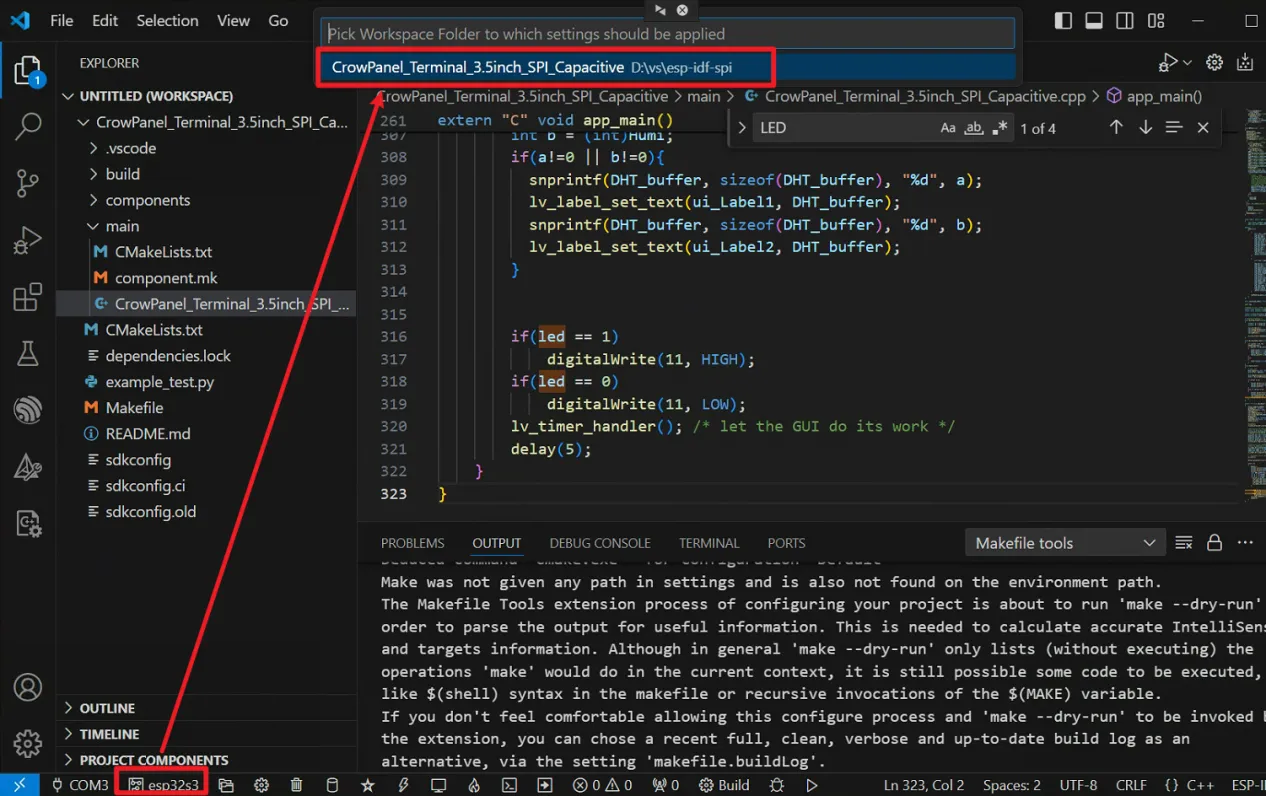
Board Setting
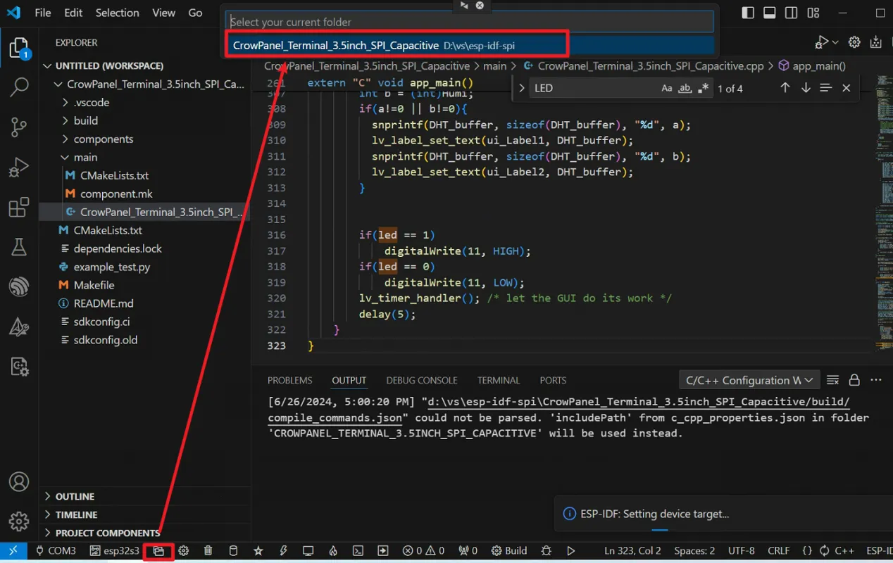
Confirm the path
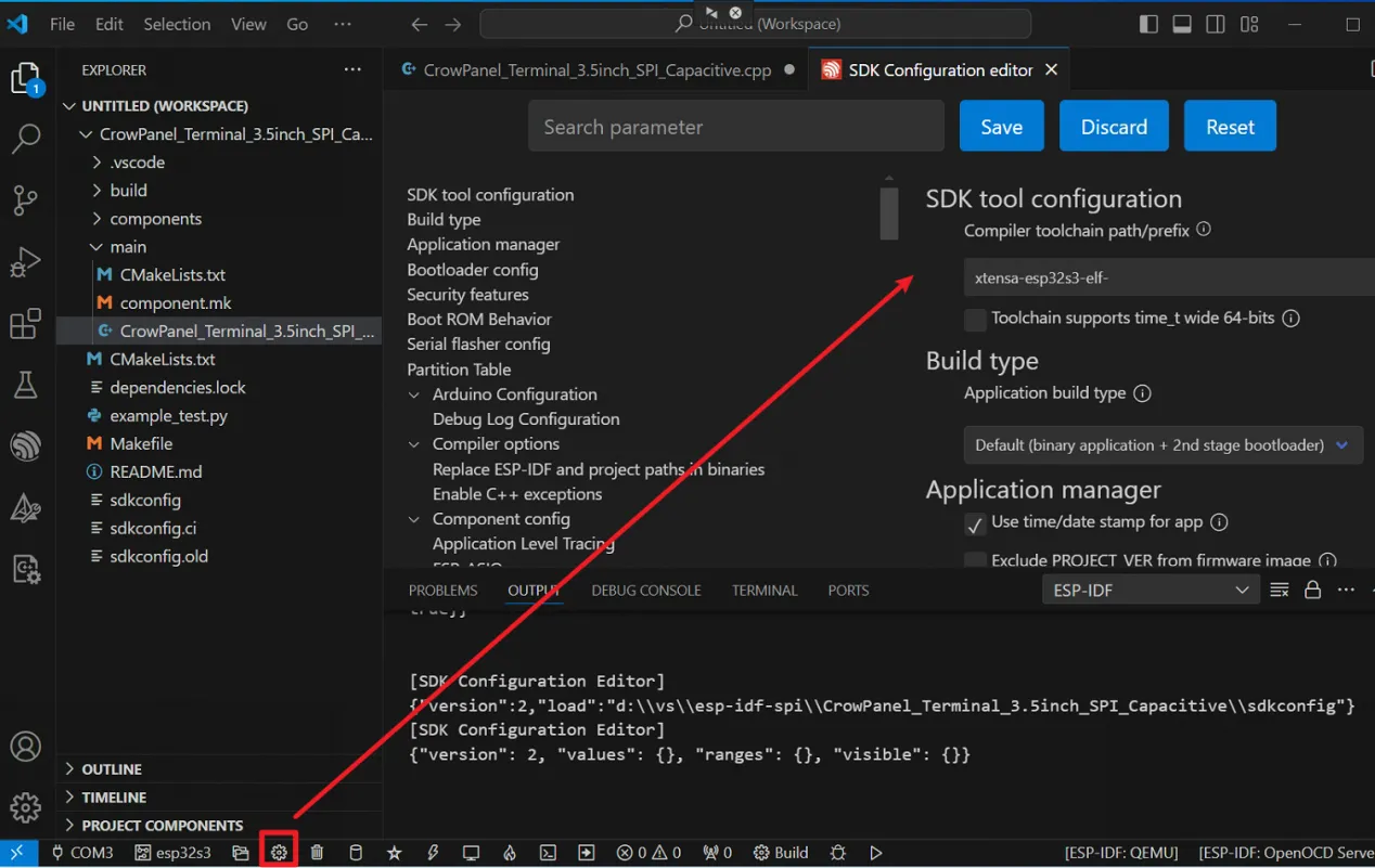
SDK Configuration
-
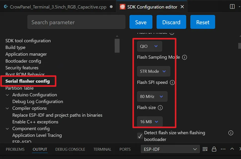
Serial flash config:
-
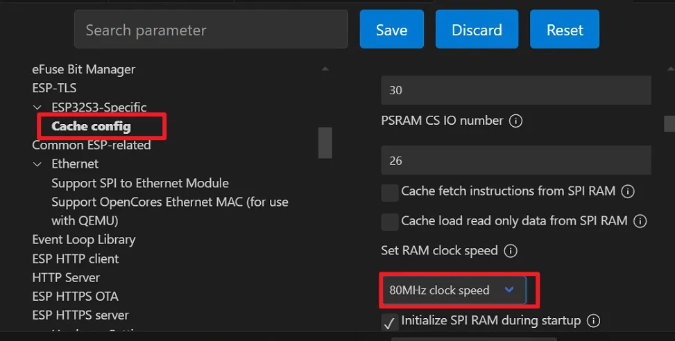
ESP32SE-Specific→Cache config:
-
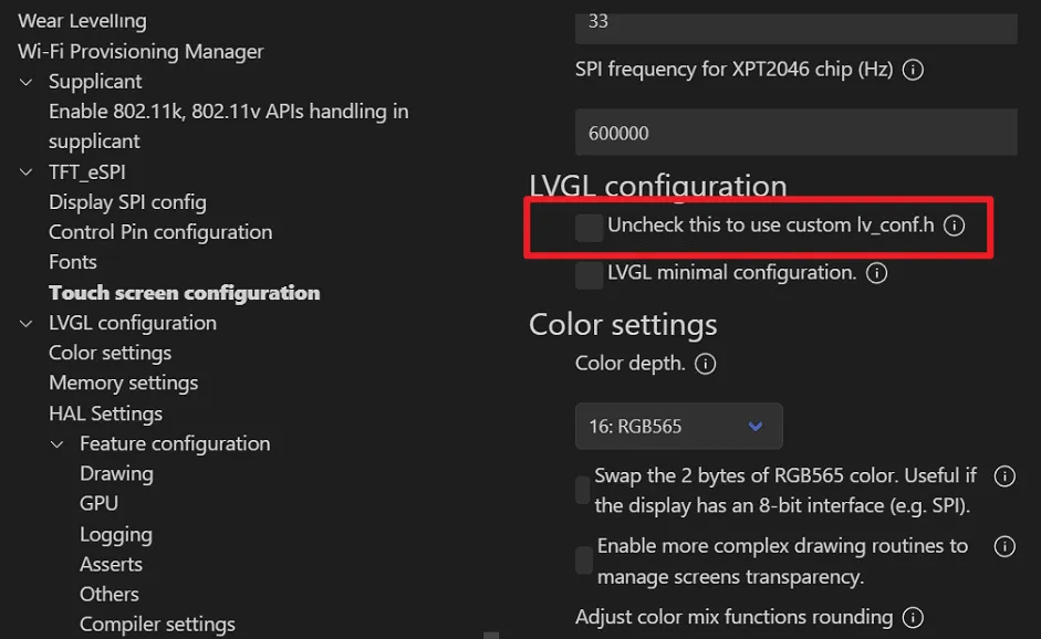
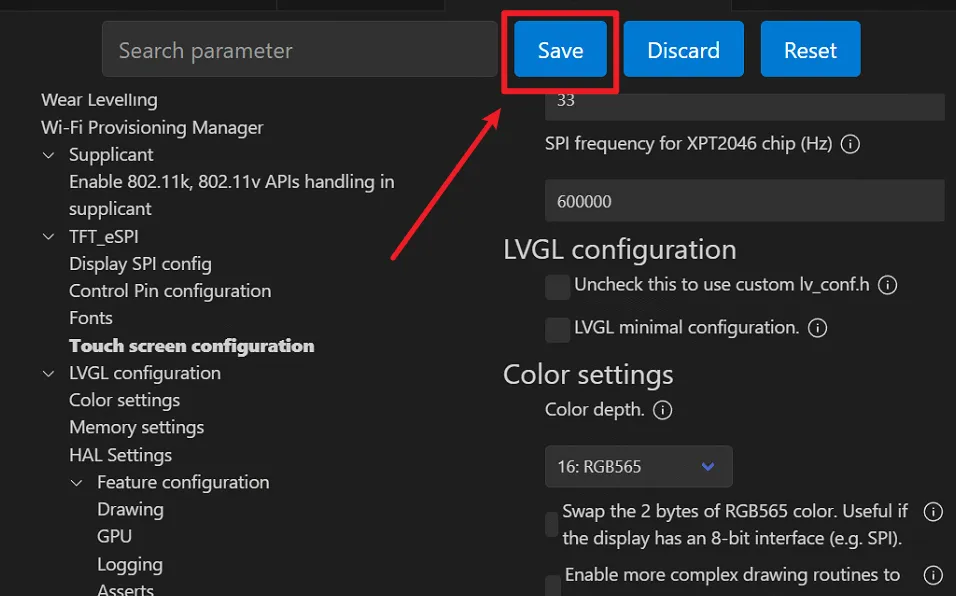
LVGL Configuration: Uncheck the "Uncheck this to use custom lv_conf.h"
-
Save the setting
Compile and upload the code
Click Compile and the compilation is successful.
Click the download button to download the program (confirm the serial port and select UART mode to download)
