5.Port Introduction
Welcome to Lesson 5 of the CrowPanel ESP32 Advance HMI Series Tutorial, Port Introduction.
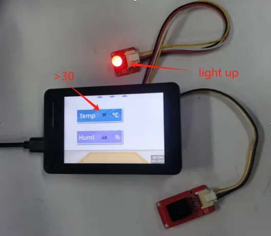
This lesson will use the IIC interface and UART1-OUT interface of this series of products to collect data from temperature and humidity sensors. When the temperature exceeds the threshold, the light bulb will automatically light up.
In this lesson, we will use the knowledge of LVGL graphics library from Lesson 3 to create an interactive interface.
1 Introduce product ports
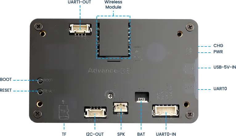
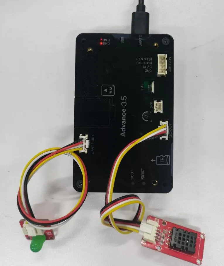
USB interface: used for power supply, serial communication, and automatic programming.
UART0-IN interface: supports power supply, serial communication, and entering manual burning mode by pressing BOOT+RESET; Other functions are consistent with the USB interface.
UART0-OUT interface: used for external power supply and serial communication.
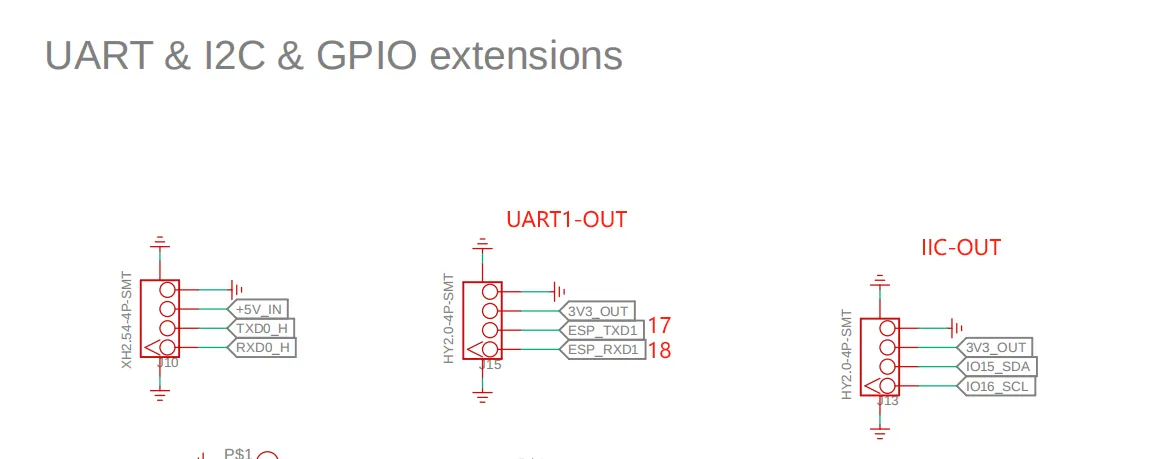
UART1-OUT interface: uses soft serial port and supports configuring IO function.
I2C-OUT interface: connects RTC chip, extended IO chip (for screen backlight, touch screen reset, power amplifier pin control) and wireless module, only supports I2C communication.
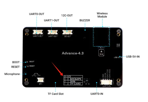
When using the UART1-OUT interface, please set the switch dial to 0 1 mode, as the wireless module and the UART1-OUT line are controlled together. (For 4.3 size, 5.0 size, 7.0 size)
2 Taking UART1-OUT interface and IIC-OUT as examples
Next, taking the external light bulb connected to the UART1-OUT interface and the temperature and humidity sensor connected to the IIC-OUT interface as an example. The temperature and humidity sensor needs to support IIC communication. The peripherals connected to the IIC interface are all like this.
In order to provide everyone with an intuitive observation, I will use LVGL to create an interactive interface.
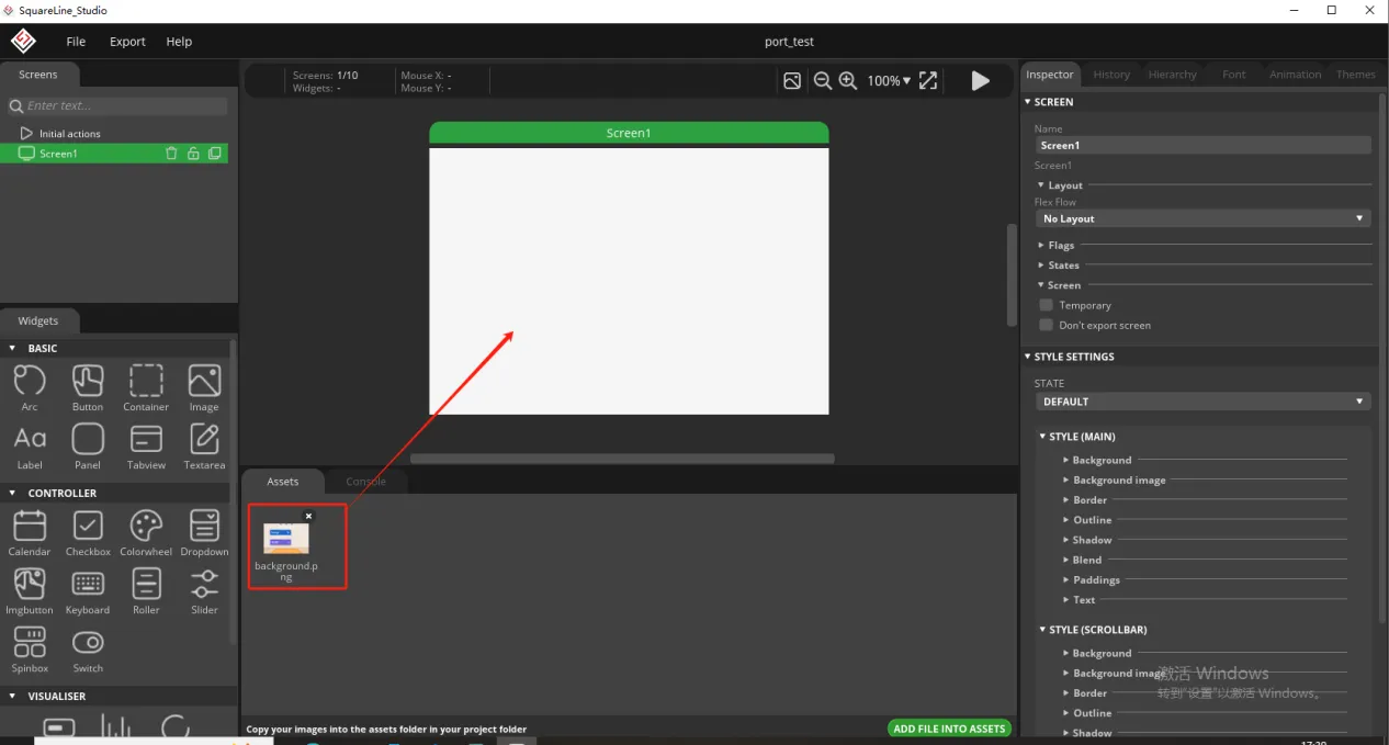
Open SquareLine Studio. If you haven't installed it, you can review the introduction of LVGL in Lesson 3.

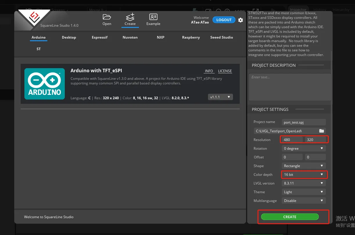
Create Arduino project
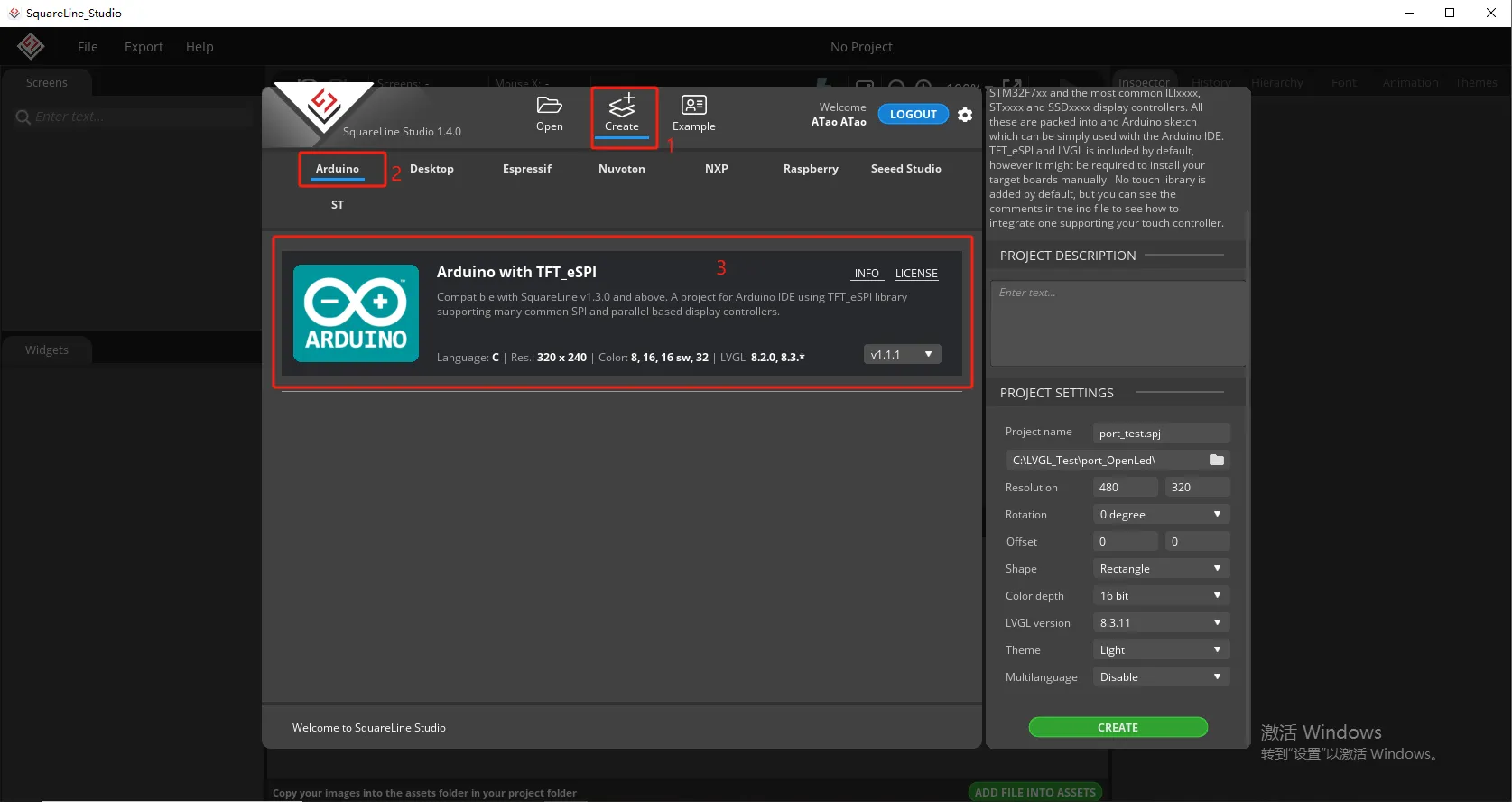
Modify the file name and file storage path according to your needs (customization is sufficient)
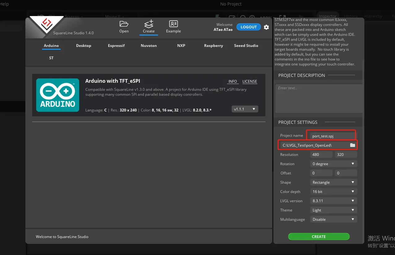
Modify the appropriate resolution based on the different sizes you are using.
Finally, click on 'Create' to proceed.
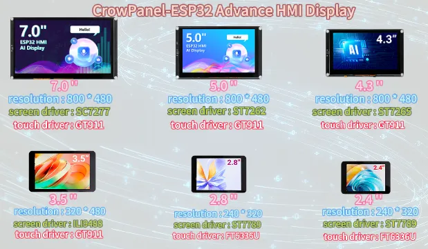
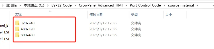
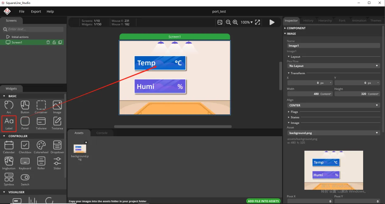
Add the background image we provide based on the resolution required for the size you are using (choose different resolutions for different sizes, refer to the resolution size used for different sizes in Lesson 3)
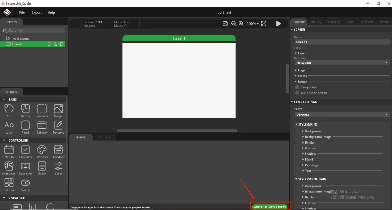
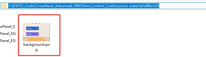
Add background image to the box.
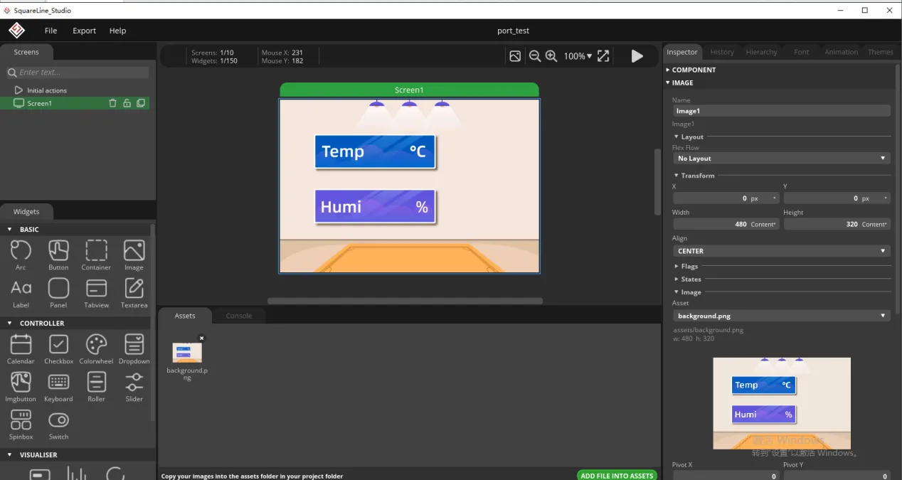
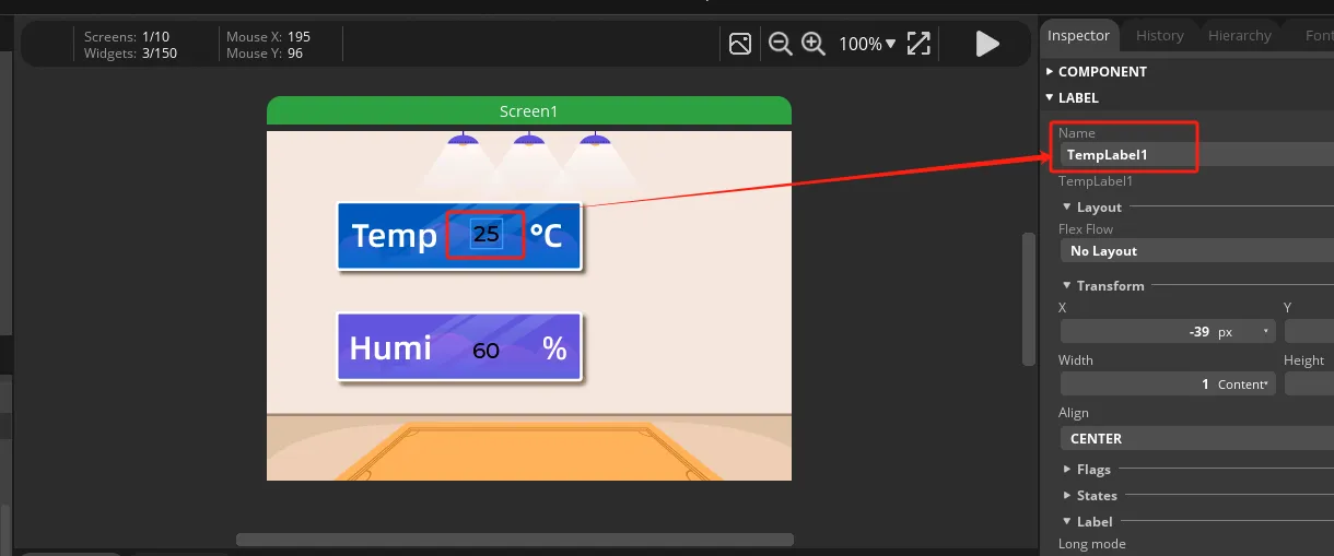
Since we need to display the temperature and humidity values on the screen, we need to add text in the two boxes for temperature and humidity.
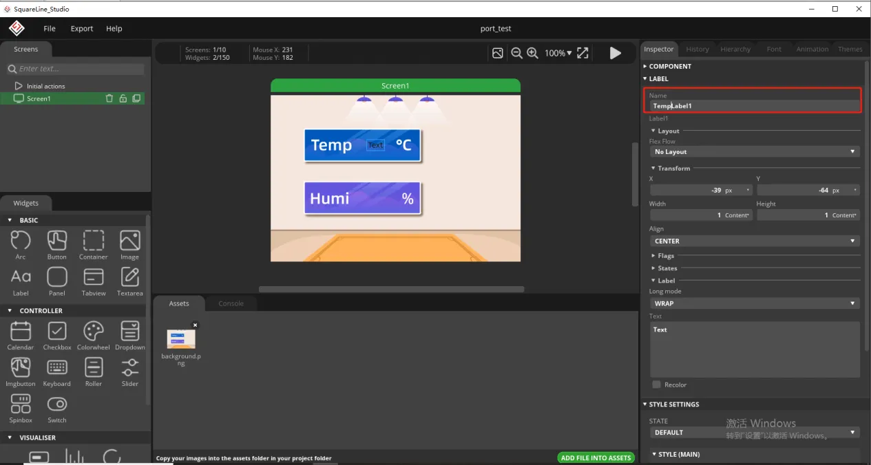
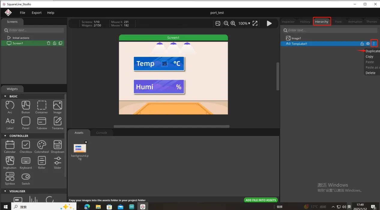
To distinguish between the other text labels that need to be created next, give this label a name to distinguish it.
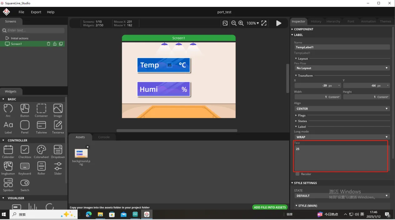
And fill in a default temperature value
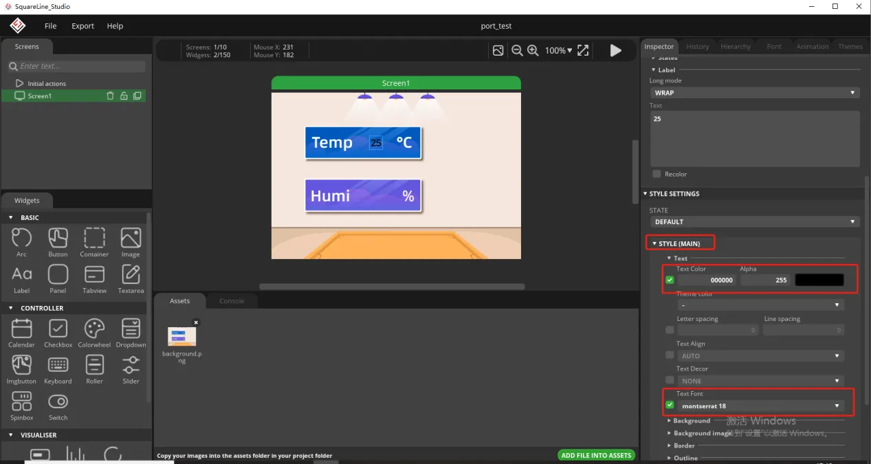
Of course, you can also set the font color and font size here
Copy the label just made and display the humidity value
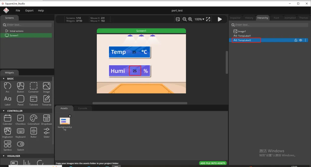
Follow the above steps to modify the humidity label
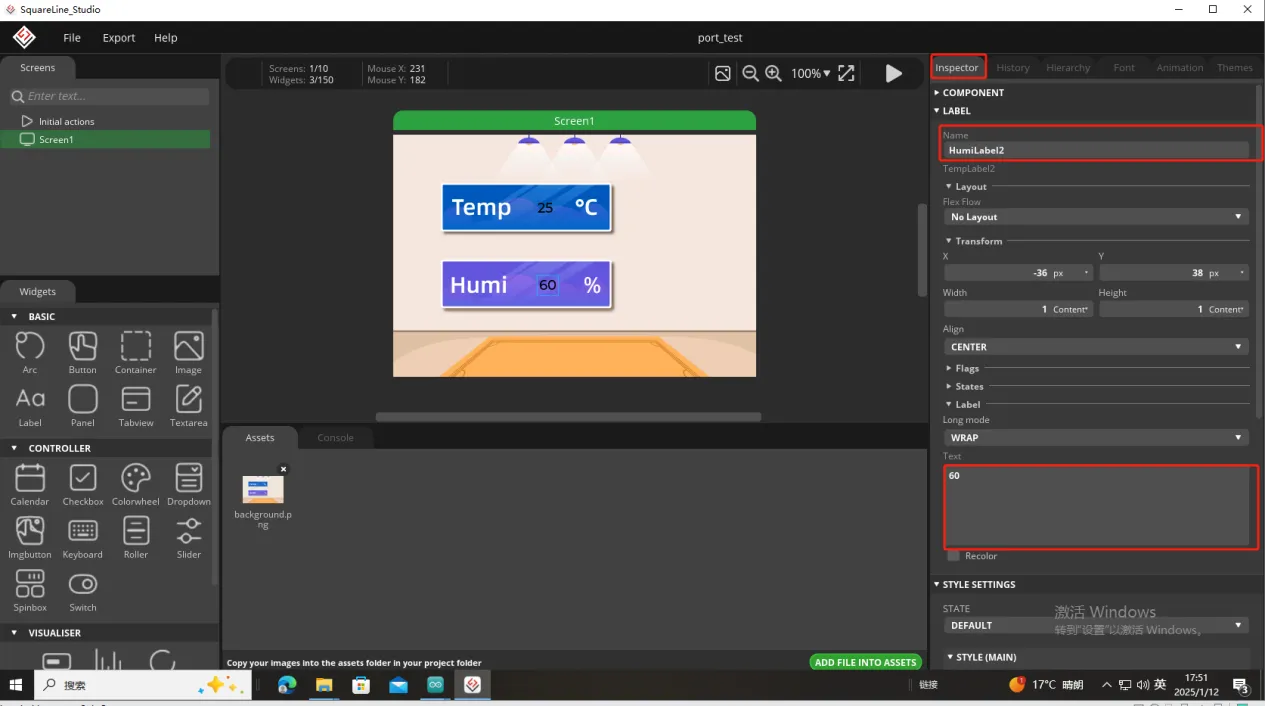
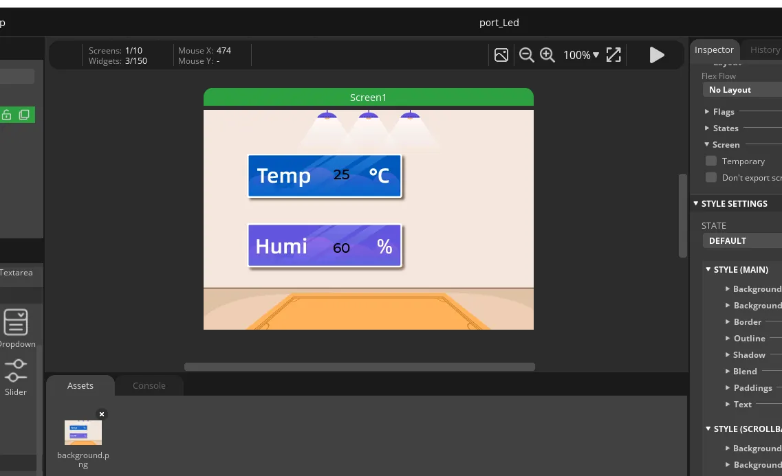
In this way, the display of temperature and humidity is completed.
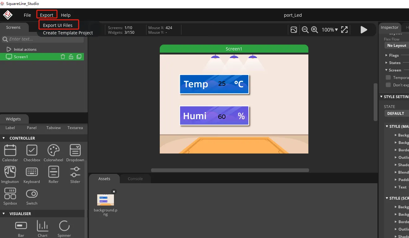
So, the UI interface we need is completed.
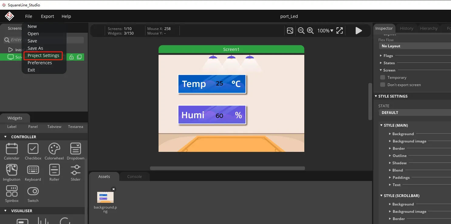
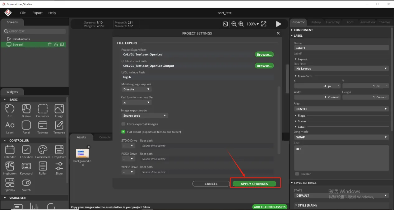
Click on Project Setting
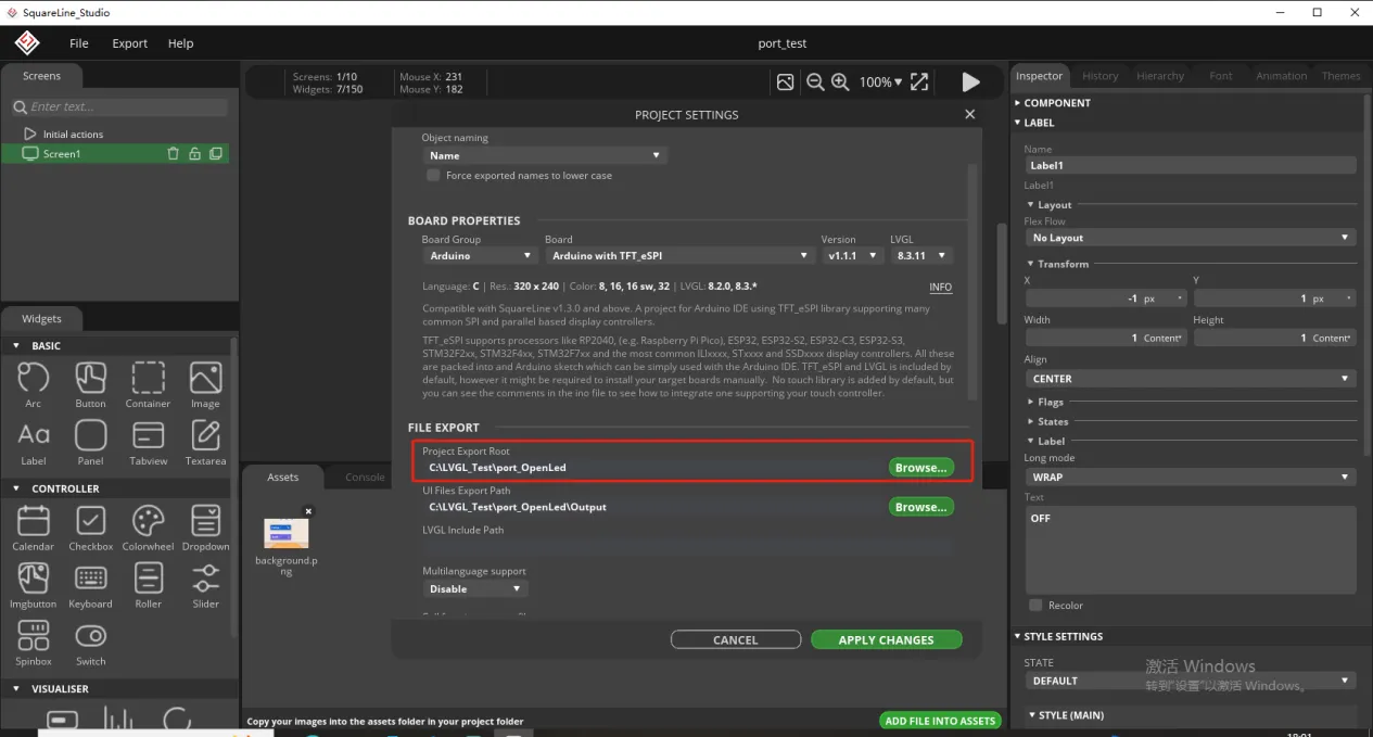
Set the file export path and customize the path
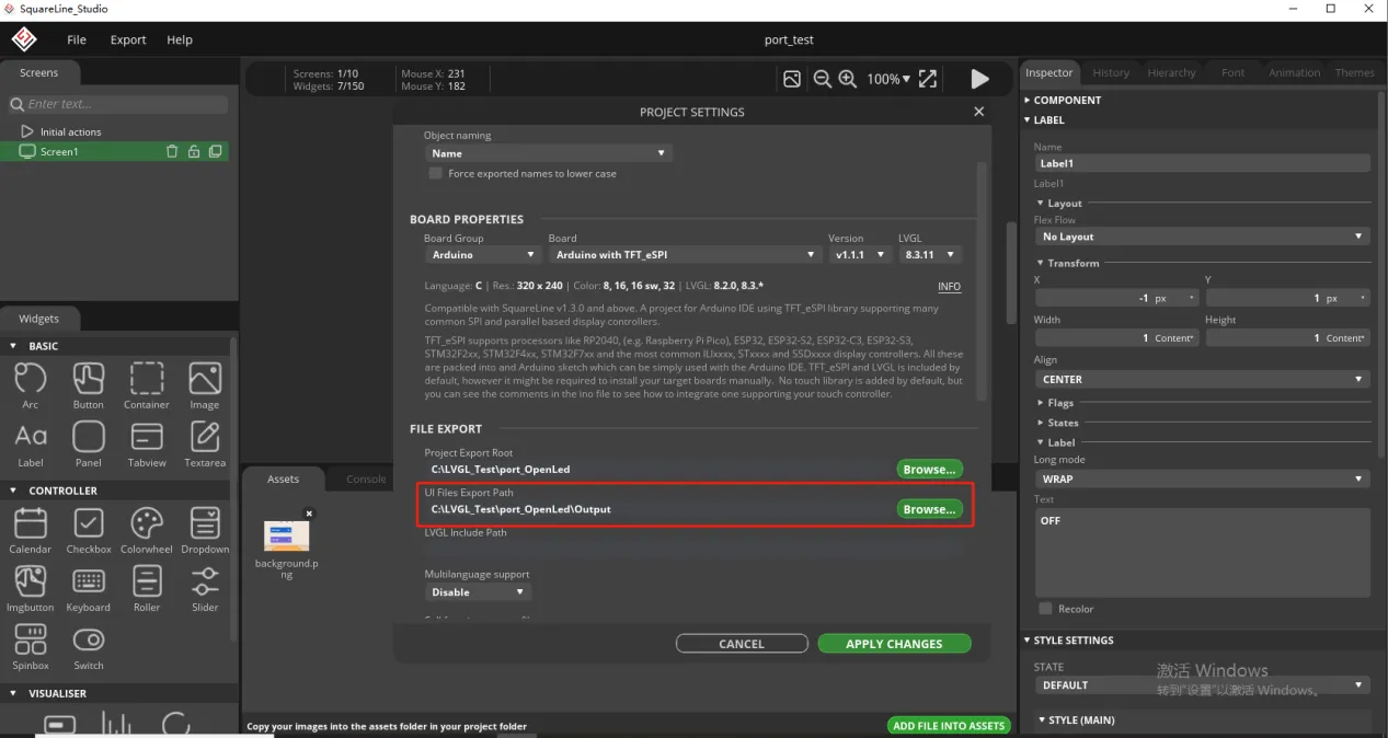
But here, you need to create an Output folder in the path above to receive the exported UI files.
Fill in lvgl. h and select Flat export.
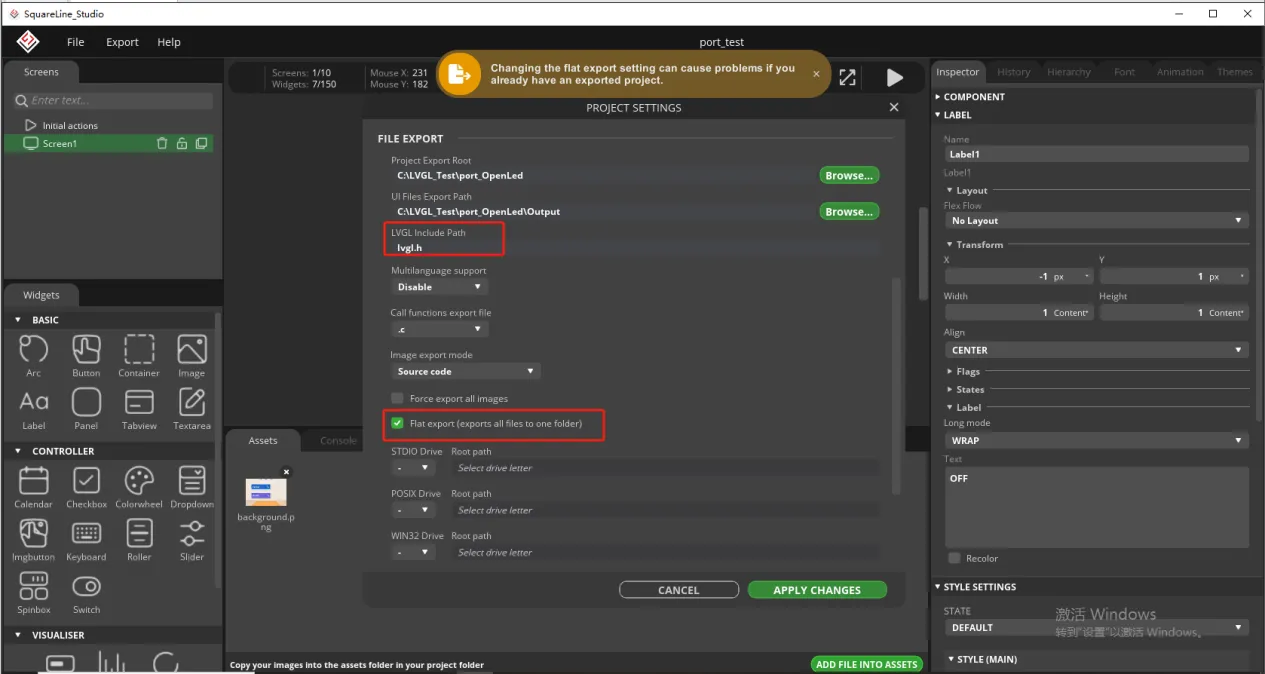
Finally confirm the settings
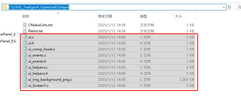
Export the designed UI interface file
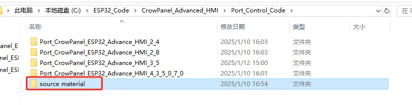
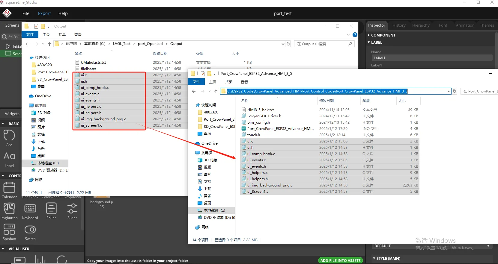
Go to the Output folder you just set up and copy the UI files you generated.
Paste it into the code file you need to open (here I will introduce the 3.5-size code as an example).
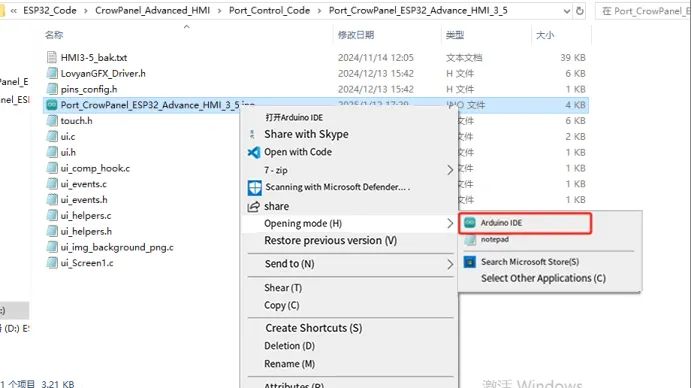
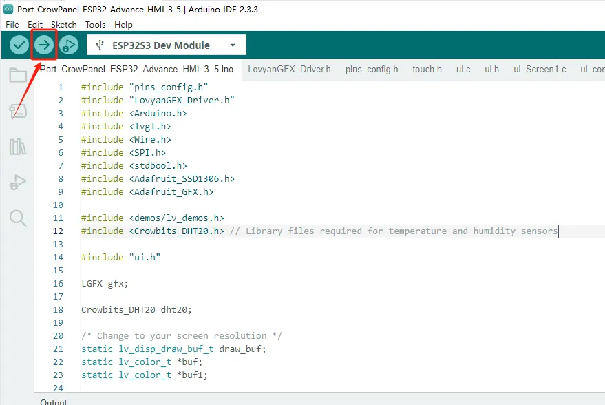
Then use Arduino IDE to open the ino file in the folder
3 Code Explanation
Introduce several key points in the code
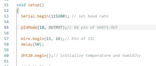
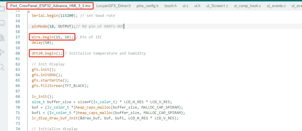
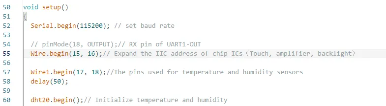
Initialize UART1-OUT pin, IIC pin, and temperature and humidity sensor
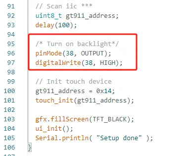
Turn on the screen backlight to enable the screen to display
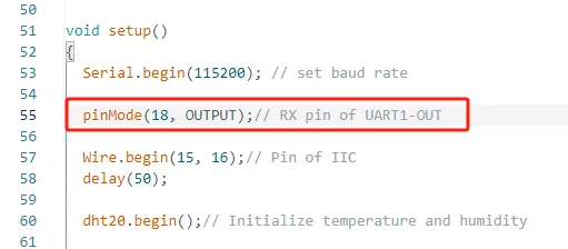
Previously, pin 18 was set as the output mode, and the UART1-OUT interface was connected to the light bulb. By controlling pin 18, the light can be controlled.
The brightness and darkness of bubbles.
Because the temperature and humidity sensor is connected to the IIC interface, it is necessary to initialize pins 15 and 16 of the IIC and initialize the temperature and humidity sensor.
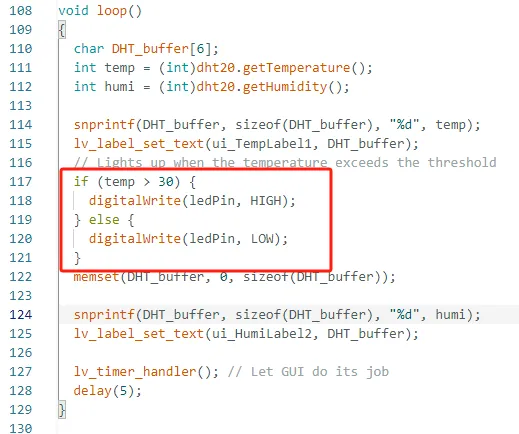
And define two variables to receive data collected by temperature and humidity sensors
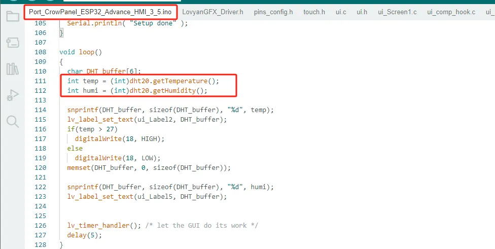
And display the value on the label you previously designed

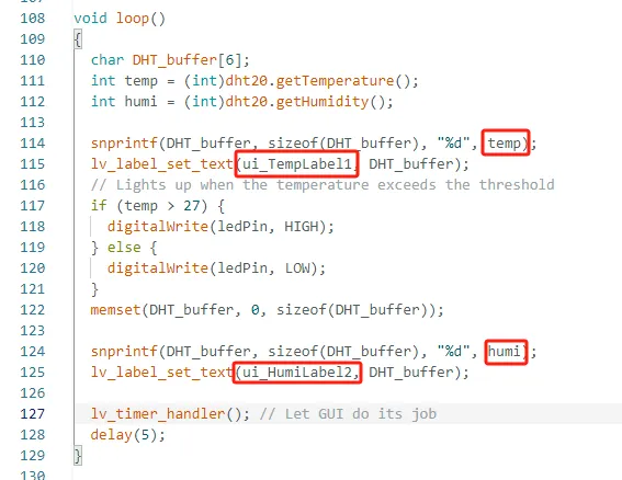
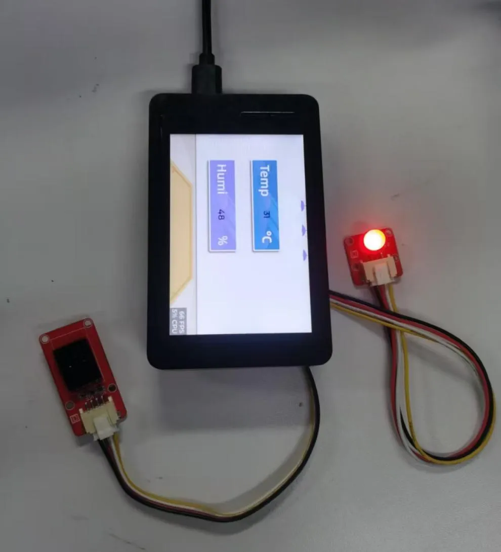
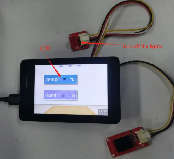
If the temperature value collected by your temperature and humidity sensor exceeds 30 ℃, the light bulb will automatically light up; If the temperature drops below 30 ℃, the light bulb will automatically turn off. (You can modify the temperature threshold yourself, this is only for the convenience of observing the results)
Special Reminder:(The following applies only to 2.8-inch and 2.4-inch products)
The IIC address of the 2.8 and 2.4 touch driver ICs is 0x38, and the IIC address of the DHT20 temperature and humidity sensor is also 0x38. When the DHT20 temperature and humidity sensor is connected to the IIC-OUT interface for use, the two addresses conflict, causing abnormal device usage. The DHT20 temperature and humidity sensor will no longer work, but will ensure the driving of the touch IC.
So in order to make the DHT20 temperature and humidity sensor work, we can connect the DHT20 temperature and humidity sensor to UART1-OUT.
Special note: The UART1-OUT interface allows the use of two or fewer IO interfaces, namely 17 and 18 pins, for your convenience. For example, when connecting a light bulb, 18 pins can be used to receive the initiated control signal. For example, doing digital input/output and analog input/output. There are also some infrared receivers, buzzers, and lights that can be connected. The premise is that you should not use more than 2 IO ports, such as SPI, which requires four IO ports to control and cannot be used.
2.4" 2.8"
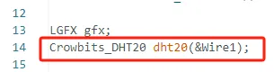
And when initializing the temperature and humidity sensor, specify the IIC pin used for initializing the temperature and humidity sensor.
4 Hardware connection
UART1-OUT connection bulb
IIC-OUT connection to DHT20 temperature and humidity sensor
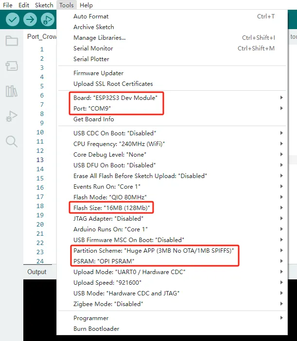
5 Configure the environment, upload code, and view phenomena
(Before uploading the code, please replace the relevant library files. Please refer to Lesson 2 for instructions on how to replace them.)
Configure the operating environment according to the guidance.
Upload code
Phenomenon display
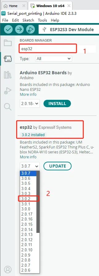
If your code compiles incorrectly, you can check if the ESP32 version number is correct. The ESP32 version number we need for this lesson is 3.0.2.
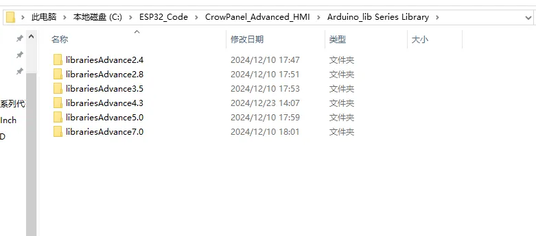
Secondly, please pay attention to replacing the corresponding size library file.
Select the appropriate library file based on the product screen size
Path reference:C:\ESP32_Code\CrowPanel_Advanced_HMI\Arduino_lib Series Library
I will use the Advance 7.0-inch product as an example for operation
Copy the Libraries Advanced 7.0 folder
Open Arduino IDE runtime library file path
Reference path: C:\Users\14175\Documents\Arduino
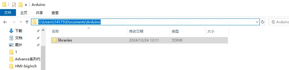
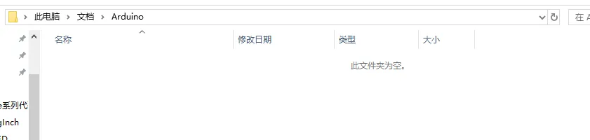
Delete the existing libraries folder
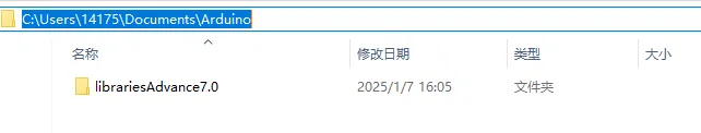
Paste the copied library Advanced 7.0 folder into this path
Change the folder name to the original libraries
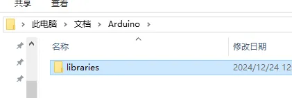
Library update completed, restart Arduino IDE.
When using other sizes, changing the library file is the same operation